System, method, and computer program for conducting optical transmission measurements and evaluating determined measuring variables

a technology of optical transmission measurement and computer program, which is applied in the direction of transmission, liquid/fluent solid measurement, amplifiers, etc., can solve the problems of high cost, complex system, and high difficulty of other systems for pre-assay irradiation of such samples, and achieve rapid and reliable operation and high reproducibility.

Inactive Publication Date: 2009-01-06
TECAN TRADING AG
View PDF13 Cites 37 Cited by
  • Summary
  • Abstract
  • Description
  • Claims
  • Application Information

AI Technical Summary

Benefits of technology

[0011]The object of the present invention is to suggest a simple, alternative method and a corresponding apparatus which allow an automatic transmission measurement to be performed on samples.
[0016]Measurements / assays may be performed with high reproducibility according to the present invention. The apparatus allows rapid and reliable functioning without manual intervention. The recognition of “serum” and / or “not serum” allows automation / simplification of numerous processes e.g., in the laboratory or clinical fields.

Problems solved by technology

However, it often happens that either the labels are selected too large or the tube diameter is selected too small and therefore—because of the overlap of the label on the circumference of the sample tube—the sample is no longer visible from the outside.
Most known systems for the pre-assay irradiation of such samples typically fail in the object of performing an automatic pre-assay even on such “hidden samples”.
Other systems are very expensive and complex.
Barcodes printed on the labels, which are also to be illuminated through, make this even more difficult.

Method used


Image

  • System, method, and computer program for conducting optical transmission measurements and evaluating determined measuring variables
  • System, method, and computer program for conducting optical transmission measurements and evaluating determined measuring variables
  • System, method, and computer program for conducting optical transmission measurements and evaluating determined measuring variables

Examples


Embodiment Construction

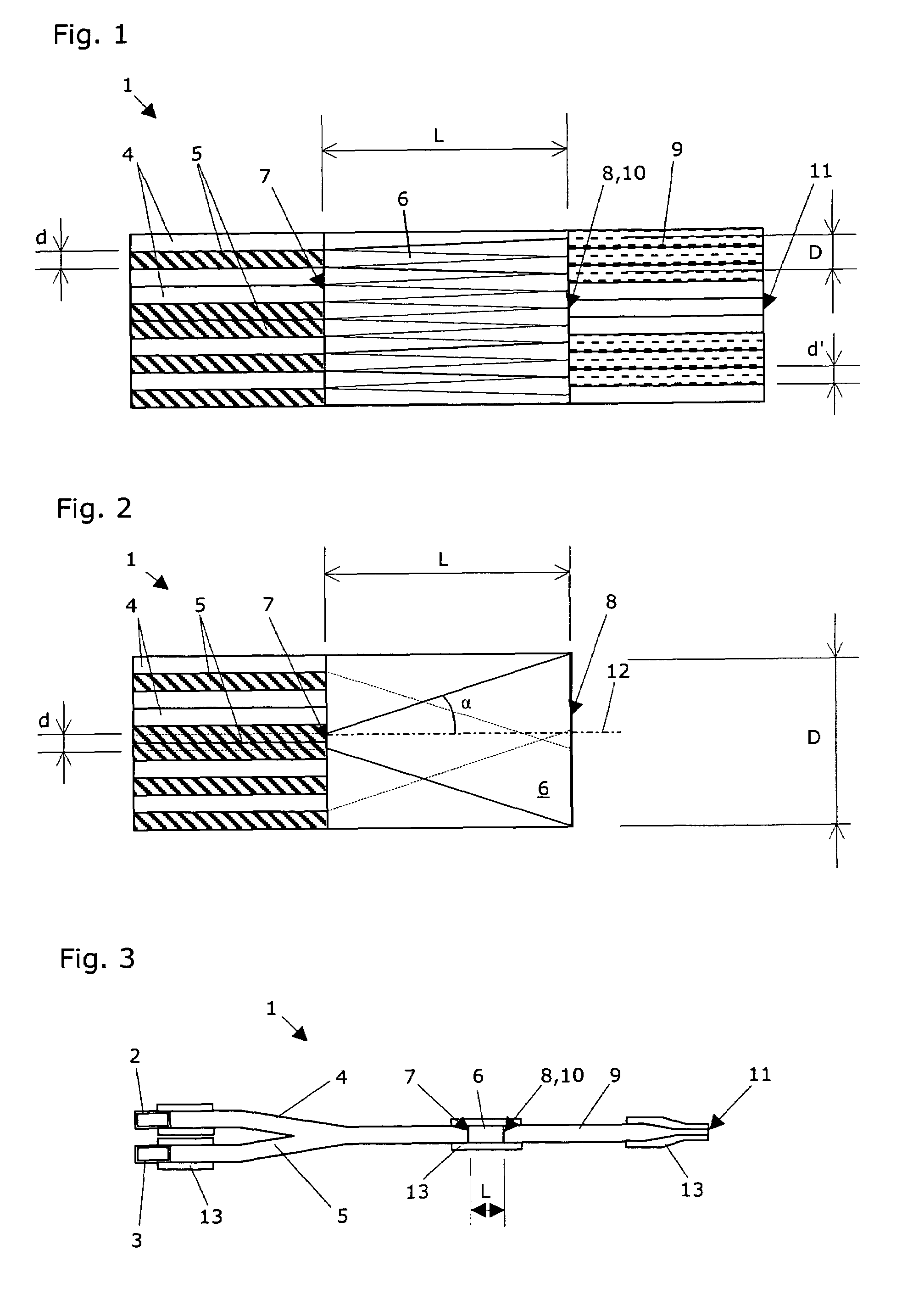
[0026]FIG. 1 shows a longitudinal section through a round mixing block which is suitable for use in a device for performing a transmission measurement according to the present invention. This mixing block is part of an optical device 1 for mixing light of different wavelengths. This device 1 is connectable to at least two light sources 2, 3, the first light source 2 emitting light having a first wavelength and the second light source 3 emitting light having a second and / or further wavelength. The device 1 includes a first light guide fiber bundle 4 for conducting the light of the first wavelength and a second and / or further light guide fiber bundle 5 for conducting the light of the second and / or further wavelength, as well as a mixing block 6. This mixing block 6 has an immission surface 7 and an emission surface 8. The fibers of the light guide fiber bundle 4, 5 have a diameter (d), they are preferably statistically intermingled with one another, and—through the densest possible pa...


PUM

PropertyMeasurementUnit
wavelengthaaaaaaaaaa

Abstract

A device for conducting a transmission measurement includes a system for generating a light wave consisting of a first and a second wavelength fraction, in addition to an optical channel guiding the light wave to a sample tube with a sample, wherein the light wave permeates the sample tube with a sample. The device also has a motion unit for producing a relative movement of the light wave along the sample tube. A receiver for receiving and separating the first and second wavelength fragments after the light wave has permeated the sample tube with a sample is also provided. A converter converts the first wavelength fraction into a first digital measuring value describing the degree of transmission in the first wavelength and converts the second wavelength fraction into a second digital measuring value describing the degree of transmission in the second wavelength. Quotients are formed from the first digital measuring values and the second digital measuring values by an evaluation system and the first derivative of the quotients is calculated.

Description

CROSS-REFERENCE TO RELATED APPLICATIONS[0001]This application claims priority on Swiss Patent Application No. CH 1681 / 01 and International Application PCT / EP02 / 10232, filed on 12 Sep. 2002, which is incorporated herein by reference.FIELD AND BACKGROUND OF THE INVENTION[0002]The present invention relates to performing optical transmission measurements and analyzing signals which are provided in this case. In particular, it relates to the automated performance and analysis of transmission measurements on sample tubes.[0003]In laboratories which are concerned with molecular biological / biochemical assays of sera or other human, animal, or plant bodily fluids, secretions, or excrements, for example, the samples to be investigated are often provided in a sample tube. The sample tubes are typically provided with a label which is used for assigning the sample to the individual from whom the sample originates. Typically, these labels also contain a computer-readable barcode or another machin...

Claims


Application Information

Patent Timeline
Patent Type & Authority Patents(United States)
IPC IPC(8): G01J5/02G01F23/00G01N21/00G01F23/292G01N21/27G01N21/31G01N21/35G01N35/10
CPCG01F23/2927G01N21/3151G01N2035/1025
Inventor BRAENDLE, HANSJOERGNADLER, ERICHGRAETER, MATTHIASBISCHOF, DANIEL
Owner TECAN TRADING AG
Why Eureka
Try Eureka