
Cell maintenance device for fuel cell stacks

a fuel cell and maintenance device technology, applied in the field of fuel cells, can solve the problems of limited hydrogen infrastructure, limited hydrogen storage capacity, and limited hydrogen storage capacity, and achieve the effects of improving hydrogen storage capacity, increasing the use of fuel cells, and increasing the difficulty of storage and transportation

Inactive Publication Date: 2009-01-06
TEXACO INC & TEXACO DEV CORP
View PDF8 Cites 6 Cited by
  • Summary
  • Abstract
  • Description
  • Claims
  • Application Information

AI Technical Summary

Benefits of technology

[0013]The invention comprises a method and apparatus for maintaining the cells of a fuel cell stack. The apparatus includes a fuel cell maintenance device comprising means for imposing a low impedance across at least one cell of a fuel cell stack, e.g. a switch, and a pulse generator. The pulse generator is capable of pulsing a cathode of the at least one cell of through the low impedance imposing means, e.g., when the switch is closed. The method transparently maintains the cells of a fuel cell stack, and comprises sequentially pulsing the cathodes of a plurality of cells in a fuel cell stack, and maintaining a consistent number of the cells providing power to a load of the fuel cell stack while sequentially pulsing the cathodes of the cell

Problems solved by technology

A significant disadvantage which inhibits the wider use of fuel cells is the lack of a widespread hydrogen infrastructure.
Hydrogen has a relatively low volumetric energy density and is more difficult to store and transport than the hydrocarbon fuels currently used in most power generation systems.
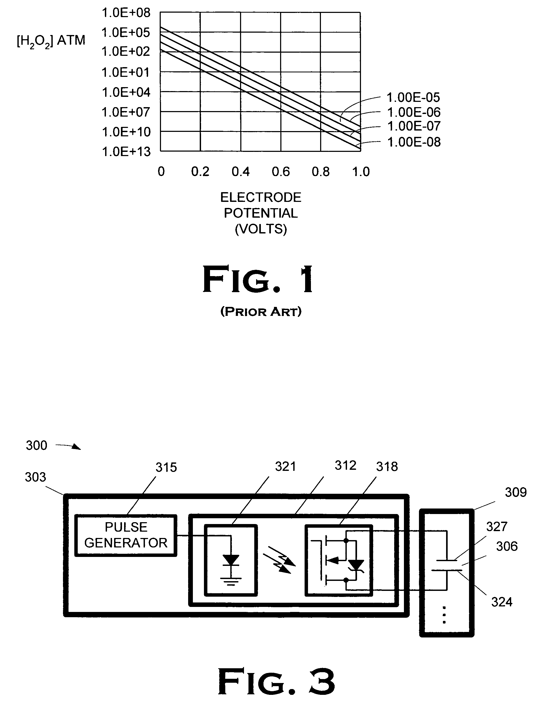
One problem arising in proton exchange membrane (“PEM”) fuel cells used with fuel processors is the formation of hydrogen peroxide on the platinum catalyst of precious metals catalyzed reactors.
The hydrogen peroxide currently limits PEM fuel cell life.
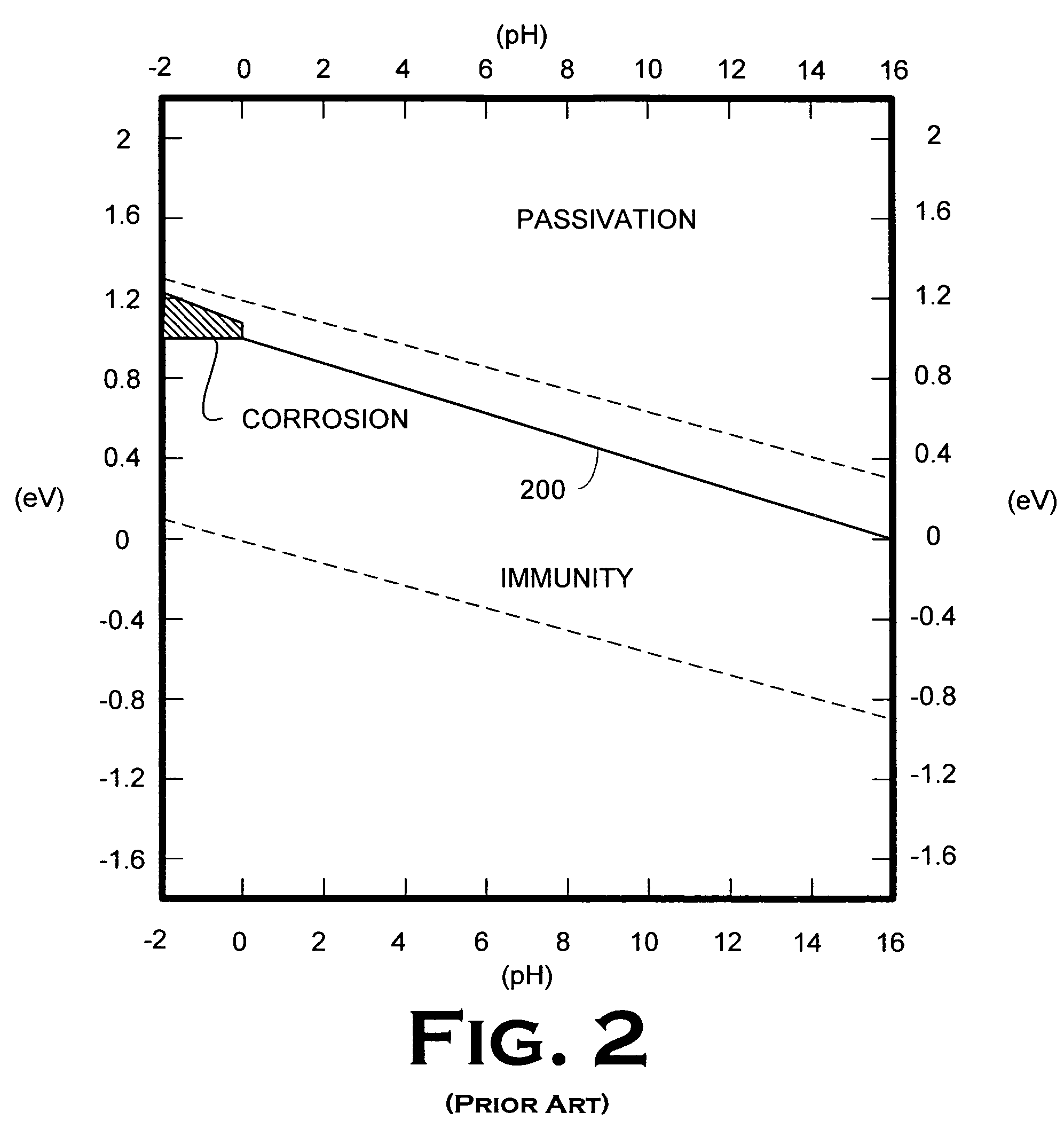
The process is also complex because the local pH has an effect on the process as well.
The problem is exacerbated by competition from alternative technologies, which are already capable generating and providing power at extremely low costs, due in part to an already installed infrastructure.
Several approaches have been proposed, but none have found commercial acceptance.

Method used


Image

  • Cell maintenance device for fuel cell stacks
  • Cell maintenance device for fuel cell stacks
  • Cell maintenance device for fuel cell stacks

Examples


embodiment 400

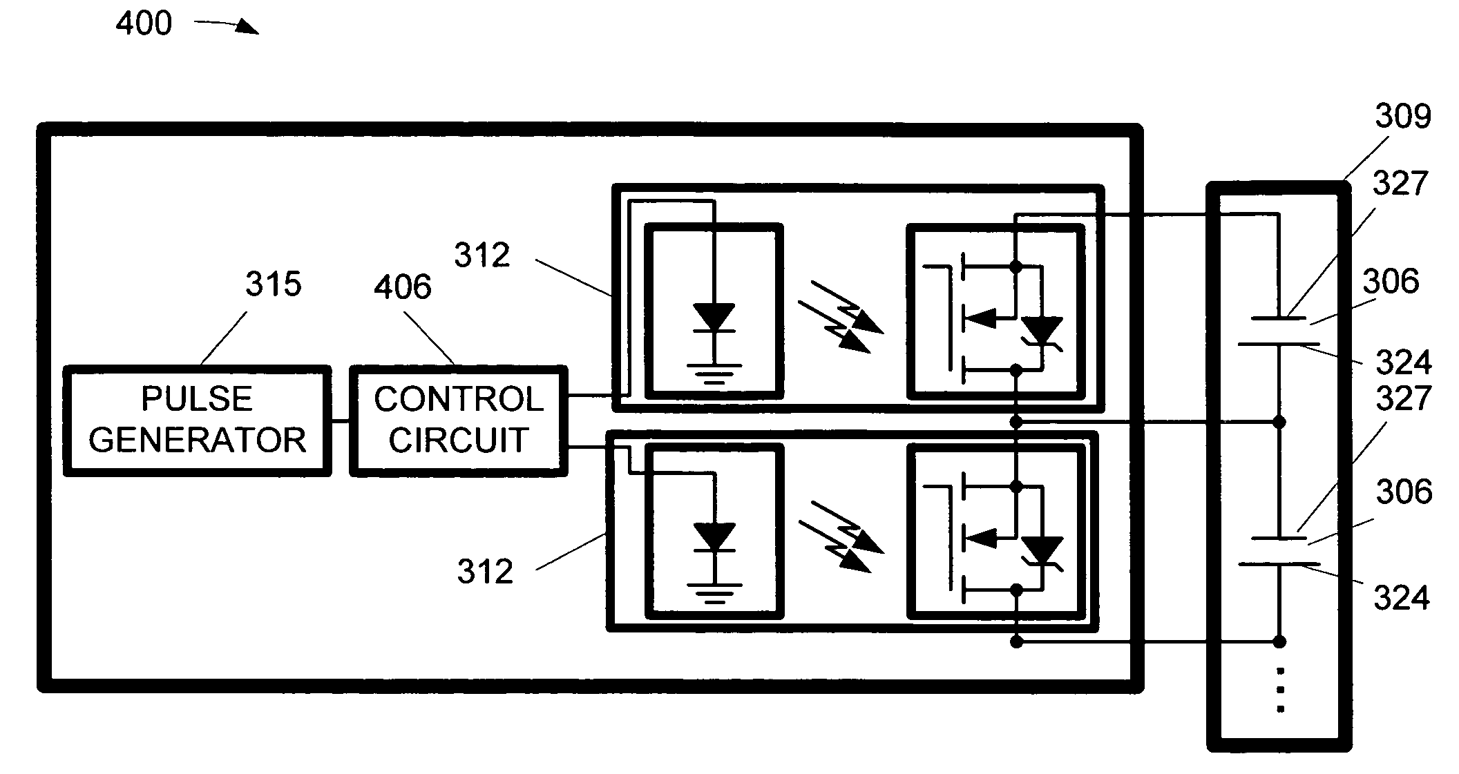
[0028]The approach shown in the embodiment of FIG. 3 for pulsing the cathode 324 of the cell 306 can be extrapolated to cover a plurality of cells 306. One such embodiment 400 is illustrated in FIG. 4A. In FIG. 4A, the fuel cell maintenance device comprises a plurality of switches 312. Each switch 312 closes to permit a pulse generator 315 to pulse the cathodes 324 of a respective cell 306. In the illustrated embodiment, a control circuit 406 closes the switches 312 serially so that the cathodes 324 of the cells 306 are pulsed serially. The pulse is transmitted to the drivers through a multiplexer. The pulse is also used to clock the counter to address the multiplexer, which sequentially selects the driver, all as is more fully disclosed below.

[0029]In some embodiments, the cathodes 324 of multiple cells 306 in the fuel stack 309 may be pulsed by the pulse generator 315 through the same switch 312. One such embodiment 412 is shown in FIG. 4B. Because there is only one switch 312, th...

embodiment 412

[0032]The pulse size is one important electrical characteristic. Pulses were varied between 0.4 V and 0.05 V across one cell, for 5 seconds every 120 seconds. Table 1 show, in columns two and three, the current densities 10 seconds and thirty seconds after the pulse. It should be noted that neither the 0.3V nor the 0.4 V pulse was run long enough to reach a stable point. The average current density would have declined further than the numbers indicated in Table 1. All else being equal, the lower the electrical potential per cell the better the performance. For practical reasons, it may be difficult to go below 0.2V per cell, but the circuitry should allow the cell to go below 0.3V. The low-voltage / high current requirement may require pulsing more than one cell at a time, e.g., as in the embodiment 412 in FIG. 4B, in some embodiments.

[0033]

TABLE 1Current Densities by Pulse SizePulse SizeBase cell(V)voltage (V)J10(ASF)J30(ASF).050.7670650.10.7670640.20.7660640.30.7660635.40.7615600

[00...

embodiment 312

[0038]The implementation of any given embodiment of the present invention will depend on the size of the fuel cell, the performance of the fuel cell, and the voltage at which the cell is run between peaks. Table 3 indicates several points of consideration when designing a cell maintenance device for a stack. Typically, bringing the cell current density from 600 to 1200 ASF was enough to drive the cell potential to 0.2 V, keeping the flows constant and set for 26 amps (600 ASF). Since the experiments were done at very low utilizations, it is likely that the actual values required for current would be less than those predicted by the tests. The values shown below are best predictions, based on experiments done with slightly less airflow. Other considerations include:[0039]the pulse voltage (listed as 0.2V) may not be sufficient to drive enough current through the external circuit in some embodiments, and it may therefore be desirable to pulse more than one cell at a time, or to have m...


PUM

PropertyMeasurementUnit
voltagesaaaaaaaaaa
saturation temperatureaaaaaaaaaa
temperatureaaaaaaaaaa

Abstract

A method and apparatus for maintaining the cells of a fuel cell stack are disclosed. The apparatus includes a fuel cell maintenance device including means for imposing a low impedance across at least one cell of a fuel cell stack, e.g., a switch, and a pulse generator. The pulse generator is capable of pulsing a cathode of the at least one cell of through the low impedance imposing means, e.g., when the switch is closed. The method transparently maintains the cells of a fuel cell stack, and includes sequentially pulsing the cathodes of a plurality of cells in a fuel cell stack, and maintaining a consistent number of the cells providing power to a load of the fuel cell stack while sequentially pulsing the cathodes of the cell.

Description

BACKGROUND OF THE INVENTION[0001]1. Field of the Invention[0002]The present invention pertains to fuel cells, and, more particularly, to a cell maintenance device for fuel cell stacks.[0003]2. Description of the Related Art[0004]Fuel cell technology is an alternative energy source for more conventional energy sources employing the combustion of fossil fuels. A fuel cell typically produces electricity, water, and heat from a fuel and oxygen. More particularly, fuel cells provide electricity from chemical oxidation-reduction reactions and possess significant advantages over other forms of power generation in terms of cleanliness and efficiency. Typically, fuel cells employ hydrogen as the fuel and oxygen as the oxidizing agent. The power generation is proportional to the consumption rate of the reactants.[0005]A significant disadvantage which inhibits the wider use of fuel cells is the lack of a widespread hydrogen infrastructure. Hydrogen has a relatively low volumetric energy densit...

Claims


Application Information

Patent Timeline
Patent Type & Authority Patents(United States)
IPC IPC(8): H01M10/46H01M8/00H01M8/04H01M8/24
CPCH01M8/04223H01M8/24H01M8/04238Y02E60/50H01M8/241H01M8/04
Inventor BAKER, HOWARD S.
Owner TEXACO INC & TEXACO DEV CORP
Learn More