Method and device for detecting leaks in respiratory gas supply systems

a ventilation system and leakage detection technology, applied in medical devices, inhalators, medical atomisers, etc., can solve the problems of insufficient integration of previously known methods and devices for determining leakage losses, and leakage can also occur in the contact area between the ventilation mask and the patient's face, so as to reduce processing work and eliminate the effect of unknown quantities

Active Publication Date: 2009-01-13
LOWENSTEIN MEDICAL TECH SA
View PDF18 Cites 86 Cited by
  • Summary
  • Abstract
  • Description
  • Claims
  • Application Information

AI Technical Summary

Benefits of technology

[0010]In accordance with the invention, this objective is achieved by designing the evaluation unit for determining the respiratory quantities of pressure and flow, by providing a storage device for at least one pair of value sequences of pressure and flow for a respiratory cycle, and by making it possible to generate at least one differential sequence for determining differential curves of compliance and resistance for at least two successive respiratory cycles.
[0011]On the basis of the determined leakage, it is possible to engineer the ventilator to supply an increased flow volume in such a way that, allowing for the leakage losses, a precisely defined useful volume flow is supplied. By taking the difference of the measured sequences of values of pressure and flow in two successive respiratory cycles, such that the selected control parameter has different control parameters in the respiratory cycles, it is possible to eliminate the effect of unknown quantities.
[0012]Direct leak detection for helping to achieve exact volume flow control is assisted by performing the computation for at least two immediately successive respiratory cycles.
[0013]To reduce the processing work, it is also possible to perform the computation for at least two respiratory cycles that are separated by at least one other respiratory cycle.

Problems solved by technology

Control of the device on the basis of volume control of the flow volume associated with a given respiratory cycle is also possible in principle but so far has been fraught with problems, because leaks can occur in the immediate area of the ventilator, in the area of the ventilation mask, and in the area of the connecting hose between the ventilator and the ventilation mask.
Leaks can also occur in the area of contact between the ventilation mask and the patient's face.
The previously known methods and devices for determining leakage losses are not yet sufficiently suitable for integration in an automatic control system for the device.

Method used


Image

  • Method and device for detecting leaks in respiratory gas supply systems
  • Method and device for detecting leaks in respiratory gas supply systems
  • Method and device for detecting leaks in respiratory gas supply systems

Examples


Embodiment Construction

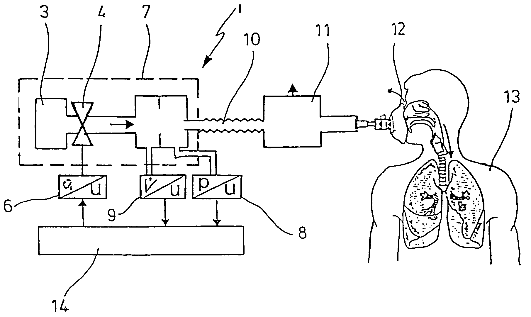
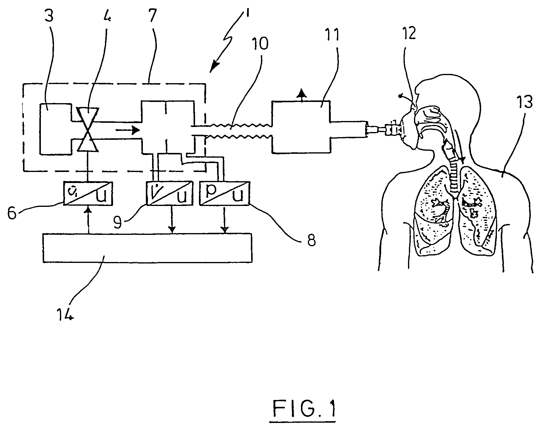
[0053]In the embodiment shown in FIG. 1, a ventilation system 1 has a driven fan 3. The fan 3 is driven by a motor or some other power source. The fan 3 is connected to a control valve 4, which has a control unit 6 and transforms a control voltage to an associated valve position.

[0054]In the illustrated embodiment, a pressure sensor 8 and a volume flow sensor 9 are connected to a ventilator 7, which consists essentially of the fan 3 and the control valve 4. The volume flow sensor 9 is typically designed as a differential pressure sensor, whose signal is converted to an associated volume flow.

[0055]The ventilator 7 is connected by a respiratory gas hose 10 and an expiration valve 11 to a ventilation mask 12, which can be positioned over the face of a patient 13.

[0056]The sensors 8, 9 are connected to an evaluation unit 14, which in turn is connected to the control unit 6.

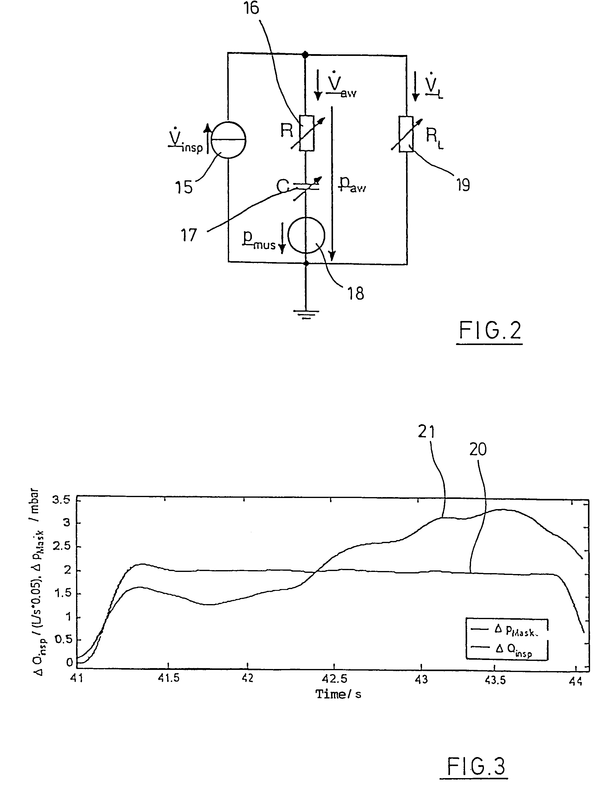
[0057]FIG. 2 shows an equivalent electrical circuit diagram, which reproduces the function of the lung of the pati...


PUM


Abstract

The invention relates to a method and a device for detecting leaks in respiratory gas supply systems. Both the pressure and the volume flow of the respiratory gas are detected and the relevant values are supplied to an evaluation device. The evaluation device is used to calculate both the respiratory parameter resistance and compliance and the leak for at least two successive breathing cycles. At least one control parameter with different signal amplitudes is pre-determined for the successive breathing cycles. The leak resistance is determined from the resulting differential sequences of pressure and flow for the successive breathing cycles.

Description

BACKGROUND OF THE INVENTION[0001]1. Field of the Invention[0002]The invention concerns a method for detecting leaks in ventilation systems, in which both the pressure of the respiratory gas and the volume flow of the respiratory gas are detected and fed into an evaluation unit.[0003]The invention also concerns a device for detecting leaks in ventilators, which has both a system for detecting the pressure of the respiratory gas and a system for detecting the volume flow of the respiratory gas, and in which the detection systems are connected to an evaluation unit.[0004]2. Description of the Related Art[0005]In the performance of ventilation, various control methods for the ventilators are used. The devices are controlled mainly by means of automatic pressure control, so that a well-defined flow volume per respiratory cycle is not determined. Control of the device on the basis of volume control of the flow volume associated with a given respiratory cycle is also possible in principle ...

Claims


Application Information

Patent Timeline
Patent Type & Authority Patents(United States)
IPC IPC(8): A61M11/00A61M16/00
CPCA61M16/0051A61M16/0066A61M2016/0021A61M2016/0039A61M2016/0042A61M2205/15A61M2230/46A61M16/022A61M2016/0027
Inventor DIETZ, FLORIANWEDLER, WOLFGANGGOBEL, CHRISTOF
Owner LOWENSTEIN MEDICAL TECH SA
Why Eureka
Try Eureka