High efficiency linear microwave power amplifier

Active Publication Date: 2009-01-13
HRL LAB
View PDF2 Cites 32 Cited by
  • Summary
  • Abstract
  • Description
  • Claims
  • Application Information

AI Technical Summary

Benefits of technology

[0022]In one embodiment, a two-stage amplifier device is presented that includes a low distortion first stage amplifier, and a high efficiency second stage amplifier coupled in series to the first stage amplifier, where a signal being received by the two-stage amplifier is post-distorted by the high efficiency second stage amplifier to compensate for a dist

Problems solved by technology

Power amplifiers generate a large amount of heat.
Heat drops the gain and increases the noise figure of the amplifier.
Heat also lowers amplifier efficiency.
Most amplifiers tend to lose gain as input power level increases.
Rather, changing the bias voltage of the same transistor changes its gain characteristics and therefore may change its class.
Other classes have a highly linear response but are not highly efficient.
For example, class B amplifiers have good efficiency but low linearity while class A amplifiers have good linearity and low efficiency.
Class AB amplifiers represent a compromise between classes A and B. Class C has a very high efficiency but will also cause a large distortion in

Method used


Image

  • High efficiency linear microwave power amplifier
  • High efficiency linear microwave power amplifier
  • High efficiency linear microwave power amplifier

Examples


Embodiment Construction

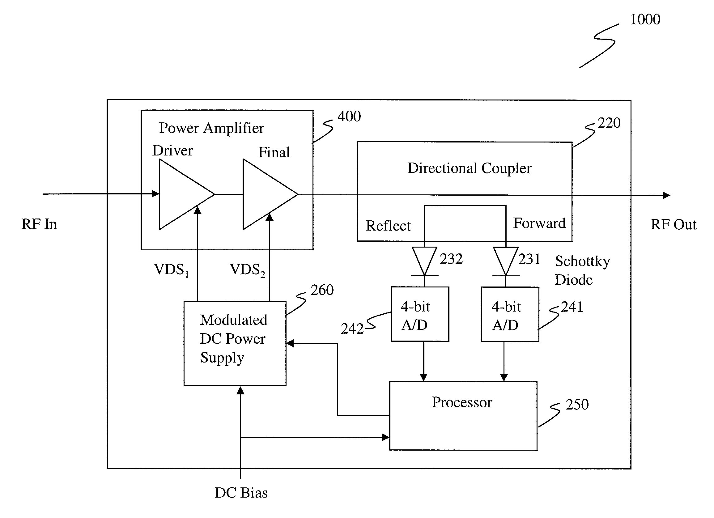
[0038]FIG. 4 shows a two-stage amplifier 400 including an exemplary arrangement of amplifier stages according to the embodiments of the present invention. In this embodiment, the pre-distortion biasing scheme used for the FETs of the two stages 10, 20 shown in FIG. 1 is reversed. In other words, in two-stage amplifier 400 of this figure, a driver amplifier 70 is formed by a class A or class AB amplifier and is followed by a power or final stage amplifier 80 formed by a class B or class C amplifier. This arrangement presents a post-distortion approach to the linearity problem.

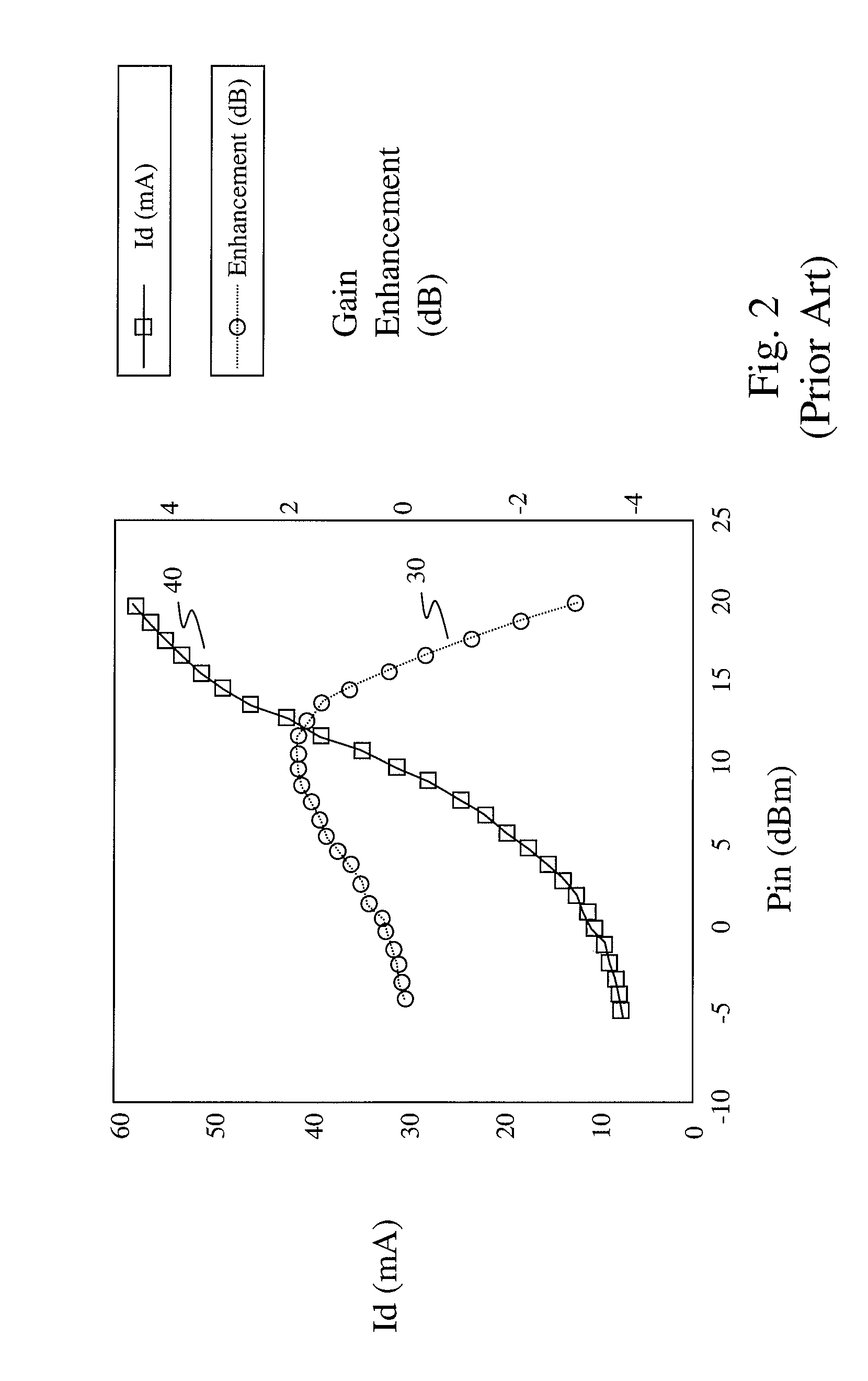
[0039]Class C amplifiers, despite their high efficiency, are rarely used in the field because their output suffers from a high degree of distortion and needs filtering. At the same time, gain expansion or gain enhancement, such as that shown in FIG. 2, mostly occurs in the high efficiency class C mode.

[0040]Combining gain expansion with class C amplifier operation offers a novel approach for compensating for the...


PUM


Abstract

A post-distortion method for cascading amplifier stages in a two-stage microwave power amplifier and a dynamic biasing method using back-end processing for correcting nonlinearity in the power amplifier output. A first or driver stage biased in a near-A region with low distortion is cascaded with a second or power stage biased in a near-C region with high efficiency. The amplitude and phase responses of the two stages compensate another to yield a more linear overall gain for the overall power amplifier. The dynamic biasing scheme modulates the source to drain voltages of the transistors used in the amplifier stages based on the harmonics in amplifier output in order to minimize the harmonics and correct non-linearity in the output.

Description

CROSS-REFERENCE TO RELATED APPLICATION[0001]This application claims the benefit of the filing date of the U.S. Provisional Patent Application Ser. No. 60 / 783,293 filed Mar. 17, 2006, the entire contents of which are hereby expressly incorporated by reference.BACKGROUND OF THE INVENTION[0002]This invention relates to the field of microwave power amplifiers and more particularly to approaches for simultaneously providing both high efficiency and low third-order intermodulation (IM3) in microwave power amplifiers using Galium Nitride High Electron Mobility Transistor (GaN HEMT) devices.[0003]Power amplifiers are used to boost a small signal to a large signal and are highly frequency dependent. Solid state GaN amplifiers may be used in the higher frequency bandwidths. Power amplifiers generate a large amount of heat. Heat drops the gain and increases the noise figure of the amplifier. Heat also lowers amplifier efficiency.[0004]Amplifier efficiency may be defined as the ratio of the out...

Claims


Application Information

Patent Timeline
IPC IPC(8): H03G5/16
CPCH03F1/0244H03F1/0272H03F3/19H03G3/004H03F2200/207H03F2200/321H03F2200/411H03F2200/451
Inventor ELLIS, GRANT ANDREWMICOVIC, MIROSLAVWANG, KEH-CHUNGMOON, JEONGSUN
Owner HRL LAB
Why Eureka
Try Eureka