
Method, system, and program product for computing a yield gradient from statistical timing

a technology of yield gradient and statistical timing, applied in the field of computer-aided design of integrated circuits, can solve problems such as circuit failure, circuit timing violation, and fraction of all manufactured circuits not meeting the required timing constraints

Inactive Publication Date: 2009-01-20
GLOBALFOUNDRIES INC
View PDF4 Cites 299 Cited by
  • Summary
  • Abstract
  • Description
  • Claims
  • Application Information

AI Technical Summary

Benefits of technology

Enables efficient optimization of integrated circuits by providing detailed yield gradients, allowing for continuous optimization and improved diagnostics across process variations, enhancing the ability to maximize performance or yield at specific requirements.

Problems solved by technology

If the delay of the critical path is more than a required value, the circuit cannot function properly.
That is, the circuit has a timing violation.
Because of variability, only a fraction of all manufactured circuits can meet the required timing constraints.
When a large number of independently variable process parameters must be modeled, the number of timing runs necessary using traditional deterministic static timing analysis makes such a method impractical.
Optimization of circuits based on deterministic timing analysis is also problematic.
Thus, guiding optimization by the results of a deterministic timing analysis may not be the most efficient way to optimize a circuit.
Unfortunately, this method does not compute yield gradients, and the sensitivities are computed by an inefficient chain-ruling method that propagates sensitivities through the timing graph.
While this approach uses the concept of a cutset, it uses a numerical perturbation method for sensitivity computation, which is neither efficient nor accurate.
While criticality computation and sensitivity analysis provide valuable diagnostics, they still do not provide sufficient data for fully optimizing a circuit.

Method used


Image

  • Method, system, and program product for computing a yield gradient from statistical timing
  • Method, system, and program product for computing a yield gradient from statistical timing
  • Method, system, and program product for computing a yield gradient from statistical timing

Examples


Embodiment Construction

[0028]As indicated above, the invention provides a method, system, and program product for continuously optimizing an integrated circuit based on yield considerations.

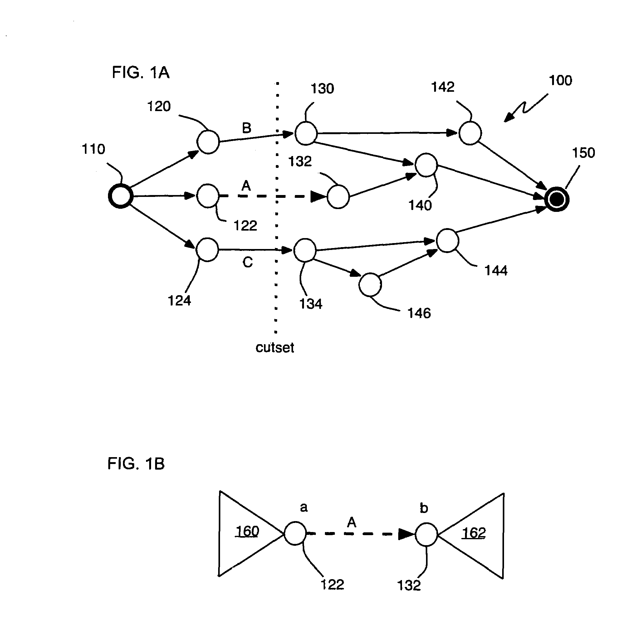
[0029]Referring now to FIGS. 1A-B, aspects of criticality probability analysis, upon which the invention is based, are shown. In FIG. 1A, a timing graph 100 is shown, comprising a plurality of nodes 110, 120, 122 . . . and edges (represented as unidirectional arrows) between pairs of nodes. As is known in the art, the first or “upstream” node 110 is designated the “source” of the timing graph and the terminal node 150 is designated the “sink” of the timing graph. The timing graph 100 of FIG. 1A is provided for purposes of explanation only. An actual timing graph may contain many more nodes and edges than those shown in FIG. 1A.

[0030]In performing a criticality probability analysis, one determines the probability of manufacturing an integrated circuit (i.e., a chip) in which a particular edge or node is included in the ...


PUM


Abstract

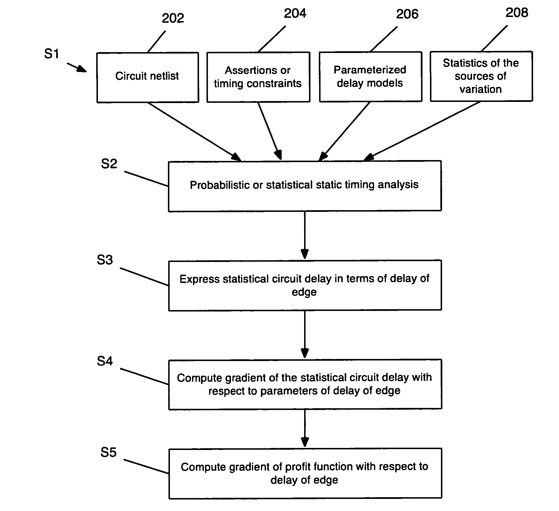
The invention provides a method, system, and program product for determining a gradient of a parametric yield of an integrated circuit with respect to parameters of a delay of an edge of a timing graph of the circuit. A first aspect of the invention provides a method for determining a gradient of a parametric yield of an integrated circuit with respect to parameters of a delay of an edge of a timing graph of the circuit, the method comprising: conducting a statistical timing analysis; expressing a statistical circuit delay in terms of a delay of the edge; and computing a gradient of the statistical circuit delay with respect to parameters of the delay of the edge.

Description

BACKGROUND OF THE INVENTION[0001]1. Technical Field[0002]The invention relates generally to computer-aided design of integrated circuits, and more particularly, to the optimization of a digital circuit based on yield considerations. Even more particularly, the invention relates to the computation of yield gradients using statistical timing.[0003]2. Background Art[0004]Variability in integrated circuits increases with each new technology generation. Sources of variability include manufacturing conditions, device fatigue, environmental variations, and phase-locked loop (PLL) variations.[0005]In the past, static timing analyses have been used to determine the performance of a circuit. In static timing analysis, a circuit is mapped to a graph called a timing graph. The longest path through the timing graph is the performance-limiting (i.e., critical) path of the circuit. If the delay of the critical path is more than a required value, the circuit cannot function properly. That is, the c...

Claims


Application Information

Patent Timeline
Patent Type & Authority Patents(United States)
IPC IPC(8): G06F17/50G06F17/10
CPCG06F17/5031G06F17/504G06F17/509G06F2217/10G06F2217/12G06F30/3312G06F30/18G06F30/3323G06F2111/08G06F2119/18Y02P90/02G06F30/3315
Inventor VISWESWARIAH, CHANDRAMOULIXIONG, JINJUNZOLOTOV, VLADIMIR
Owner GLOBALFOUNDRIES INC
Learn More