

Plasma process system and plasma process method
a plasma process and plasma technology, applied in the direction of coatings, chemical vapor deposition coatings, electric discharge tubes, etc., can solve the problems of increasing the number of parts of the system, complicating the system structure, uneven film thickness distribution on the substrate surface underwent film deposition, etc., to achieve high uniformity
- Summary
- Abstract
- Description
- Claims
- Application Information
AI Technical Summary
Benefits of technology
Problems solved by technology
Method used
Image

Examples
first embodiment
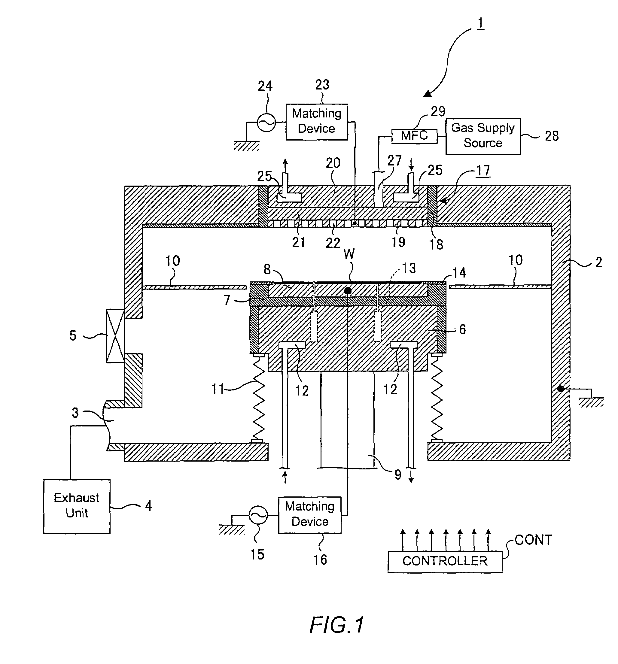
[0047]FIG. 1 shows a cross-sectional view of a plasma process system 1 according to the first embodiment of the invention
[0048]As shown in FIG. 1, the plasma process system 1 has an approximately cylindrical chamber 2. The chamber 2 is made of a conductive material such as aluminum, subjected to an alumite process (anodic oxidation). The chamber 2 is grounded.
[0049]An exhaust port 3 is provided in the bottom portion of the chamber 2. An exhaust unit 4 which comprises a turbo molecular pump or the like is connected to the exhaust port 3. The exhaust unit 4 vacuums inside the chamber 2 to a predetermined depressurized atmosphere, e.g., 0.01 Pa or lower. A gate valve 5 which is openable and closable airtightly is provided on a side wall of the chamber 2. With the gate valve 5 open, transfer-in and transfer-out of a wafer W is performed between the chamber 2 and an adjoining loadlock chamber (not shown).
[0050]A susceptor support 6 with an approximately columnar shape stands upright from...
second embodiment
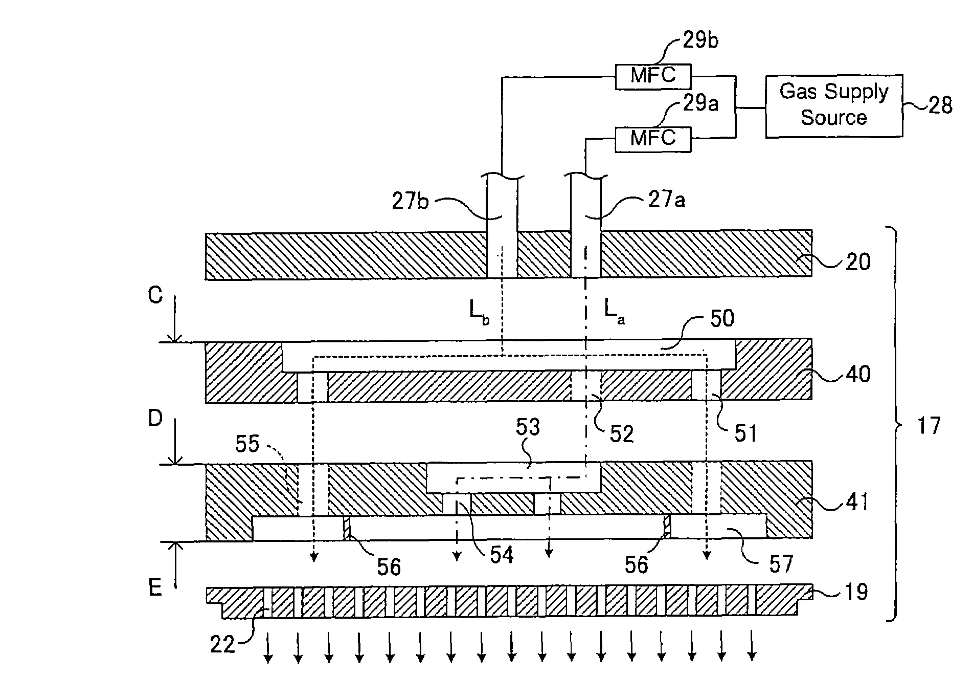
[0084]A process system according to the second embodiment has the same structure as the plasma process system 1 illustrated in FIG. 1 except for the upper electrode 17. FIG. 5 shows an exploded diagram of the upper electrode 17 according to the second embodiment. For easier understanding, in FIG. 5, same reference symbols are given to those portions which are the same as those in FIG. 2 and the description will be omitted.
[0085]In the second embodiment, the process gas is supplied to the center portion and end portion of a wafer W at the flow rates independently controlled. That is, as shown in FIG. 5, a center-portion gas supply tube 27a and an end-portion gas supply tube 27b are connected to the electrode support 20 and are connected to the common gas supply source 28 respectively via flow-rate control devices 29a and 29b.
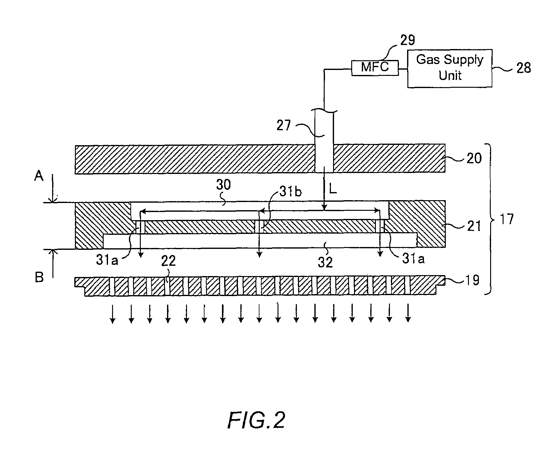
[0086]The process gases supplied from the center-portion gas supply tube 27a and end-portion gas supply tube 27b respectively are diffused, passing through a ce...
examples
[0107]Process conditions that provided the best uniformity, such as deposition speed uniformity, were studied for various films. The results are shown in FIG. 11. In FIG. 11, SiO2, SiOF, SiC, SiN, SiCN, CF*x, SiCH and SiCO were studied. The gas seeds are not limited to those in the diagram, but SiH4 may be substituted with TEOS or the like, SiF4 may be substituted with Si2H2F2 or the like, CH4 may be substituted with C2H6 or the like, C6F6 may be substituted with CF4 or the like, N2 may be substituted with N2O, NO or the like, O2 may be substituted with N2O, CO2 or the like, and 3MS (trimethylsilane) may be substituted with methylsilane, dimethylsilane or the like. The substitutable gases are shown in FIG. 12.
[0108]As shown in FIG. 11, the process condition can be optimized according to the deposition seeds by adequately changing the ratio of the center area to the end area.
[0109]According to the second embodiment, as described above, the second recess 57 that is connected to the ga...
PUM
| Property | Measurement | Unit |
|---|---|---|
| Flow rate | aaaaa | aaaaa |
Abstract
Description
Claims
Application Information