Transretinal implant and method of implantation

a technology of retinal implants and medical devices, applied in the field of implantable retinal medical devices, can solve the problems of large size inability to produce adequate simulated vision to truly aid the visually impaired, and large volume of early prosthesis devices

Inactive Publication Date: 2009-01-27
DOHENY EYE INST +1
View PDF9 Cites 32 Cited by
  • Summary
  • Abstract
  • Description
  • Claims
  • Application Information

AI Technical Summary

Problems solved by technology

While some of these early attempts met with limited success, early prosthesis devices were large, bulky and could not produce adequate simulated vision to truly aid the visually impaired.
These diseases, however, often spare much of the remaining inner retinal layers of the outer nuclear, outer plexiform, inner nuclear, inner plexiform, ganglion cell, and nerve fiber layers.
The nerve fiber layer generally runs radially with many layers of overlapping fibers from different portions of the retina making selection of the appropriate nerve fiber to stimulate difficult.
No discrete surface structure restricted the directional flow of charges, thereby preventing any resolution capability.
The presence of holes of various geometries was not helpful to permeation of oxygen and biological substances.
However, in many instances such drugs are not capable of being administered either orally or intravenously without the risk of various detrimental side effects.
For example, intravenous ganciclovir (GCV) is effective in the treatment of CMV retinitis in AIDS patients, but bone marrow toxicity limits its usefulness.
It is further limited by the risk of sepsis related to permanent indwelling catheters and the inability to receive concurrent therapy with zidovudine (AZT).
While these capillary openings in this construction are effective for releasing certain drugs to the eye, they add considerable complexity to the manufacture of the device because it is difficult to control the size of these openings in large-scale manufacturing using various polymers.
Nonetheless, as described in U.S. Pat. No. 4,014,335, certain problems have been identified with such devices such as the difficult task of sealing the margins of the membrane to form the container.
In addition, stresses and strains introduced into the membrane walls from deformation during manufacturing of those devices may cause the reservoir to rupture and leak.
However, there are many disadvantages associated with their use including the fact that it is often difficult to obtain the desired release rate of the drug.
If relatively high levels are required inside the eye, such devices are ineffective.

Method used


Image

  • Transretinal implant and method of implantation
  • Transretinal implant and method of implantation
  • Transretinal implant and method of implantation

Examples


Embodiment Construction

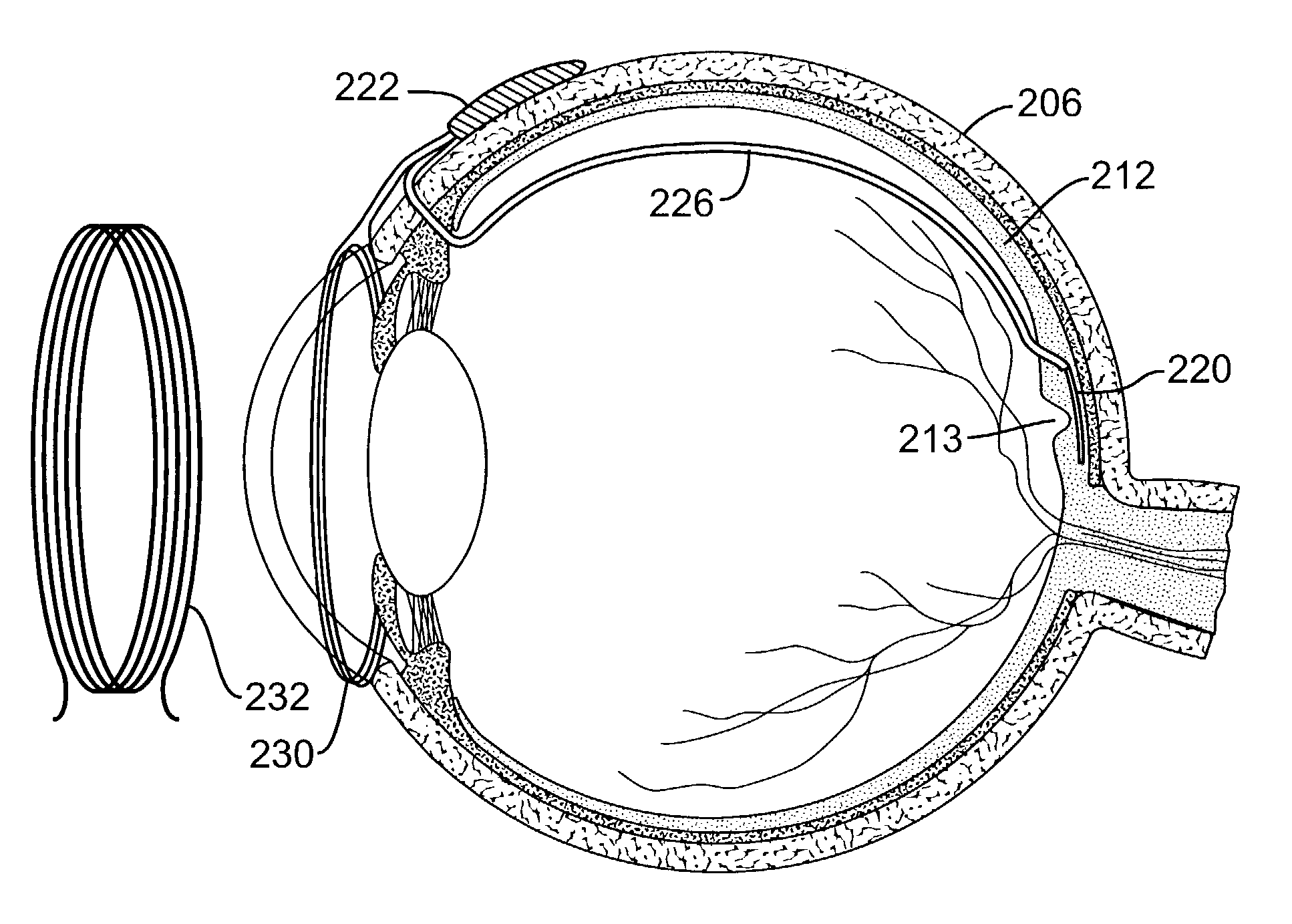
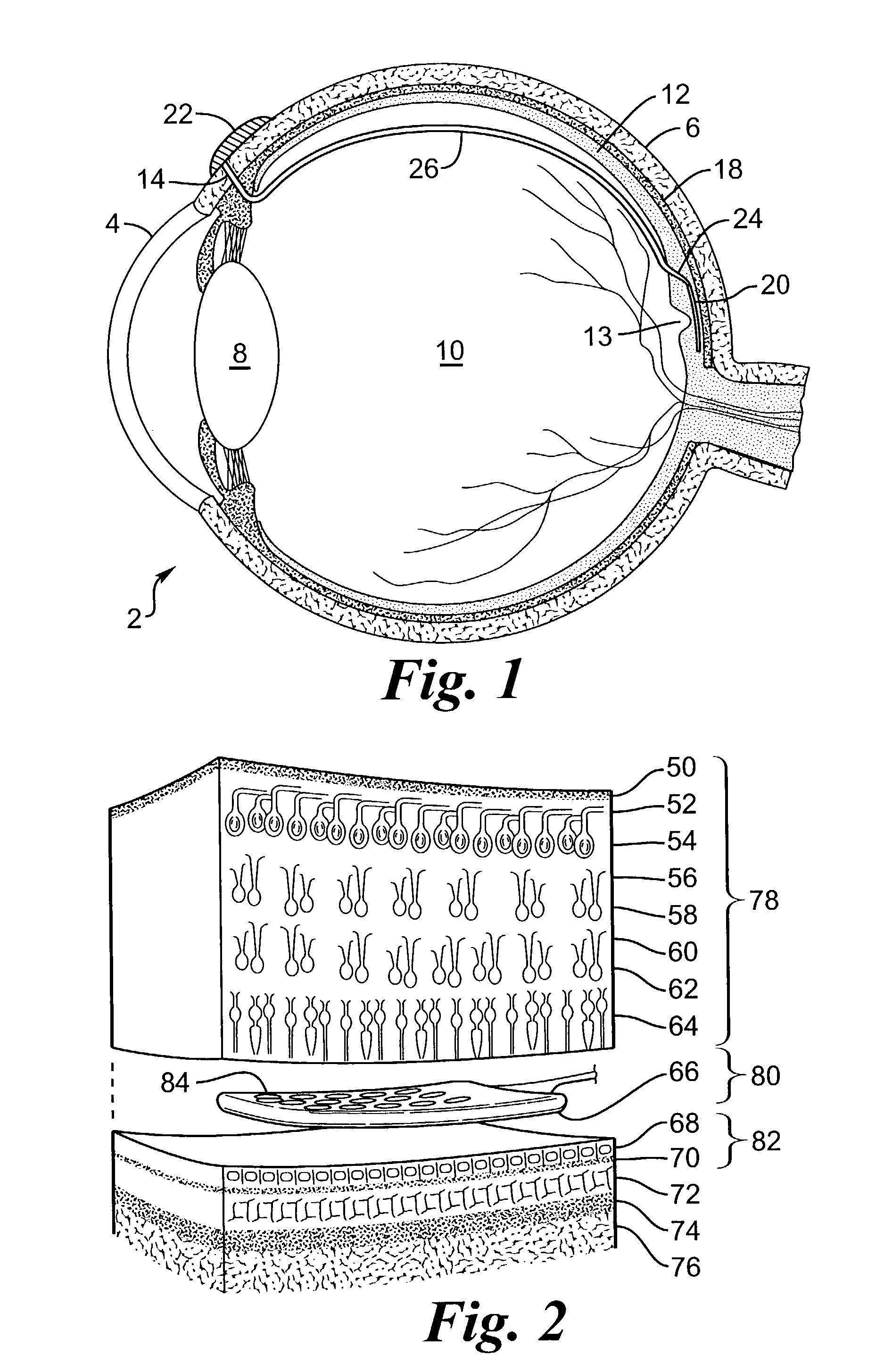
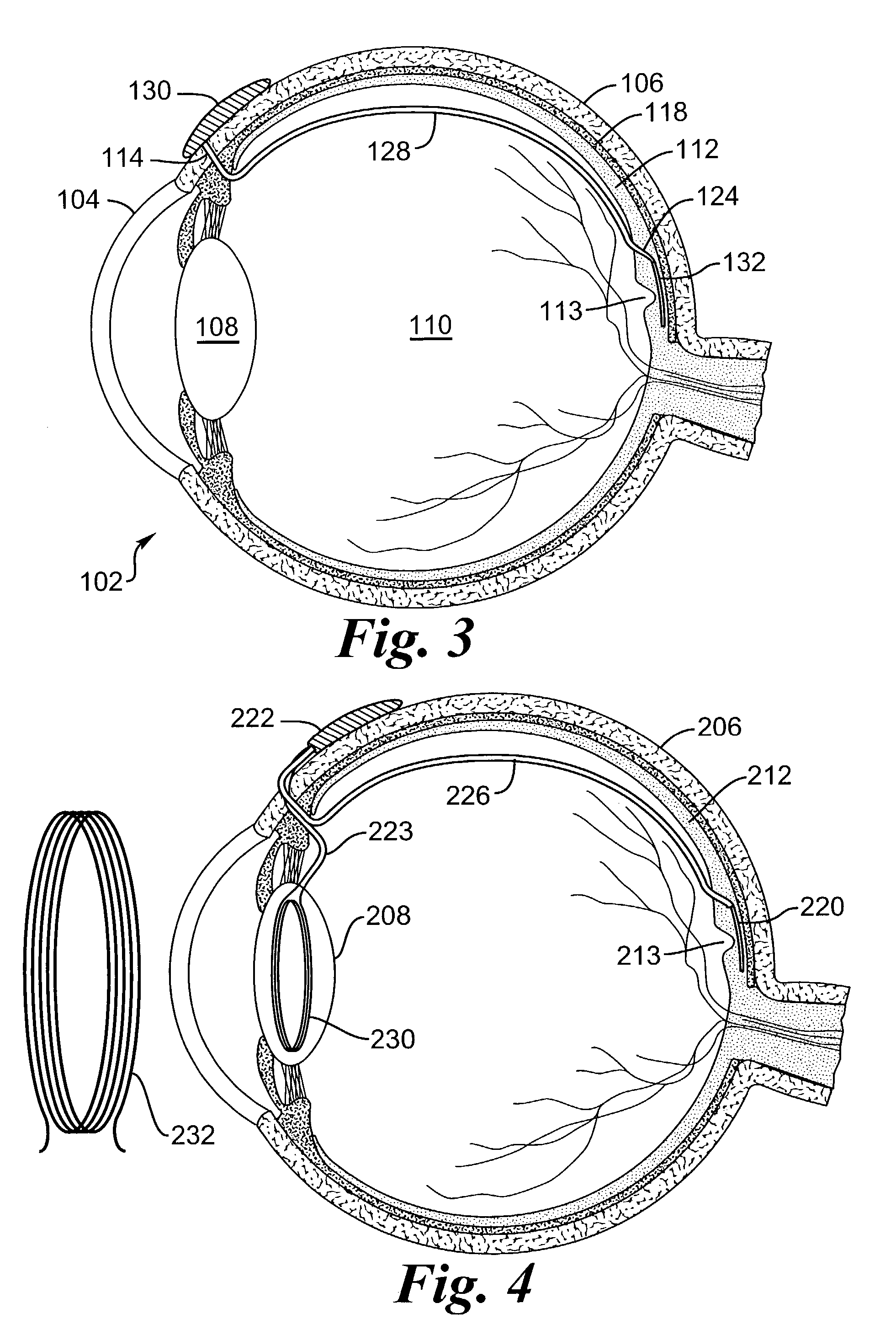
[0050]FIG. 1 provides a cross-sectional view of a preferred embodiment of the eye 2 with a retinal implant 20 placed subretinally. The current invention involves the use of an electronic device, a retinal implant 20 that is capable of mimicking the signals that would be produced by a normal inner retinal photoreceptor layer. When the device is implanted subretinally between the inner and outer retinal layers, it will stimulate the inner layer to provide significantly useful formed vision to a patient whose eye no longer reacts to normal incident light on the retina 12. Patient's having a variety of retinal diseases that cause vision loss or blindness by destruction of the vascular layers of the eye, including the choroid, choriocapillaris, and the outer retinal layers, including Bruch's membrane and retinal pigment epithelium. Loss of these layers is followed by degeneration of the outer portion of the inner retina, beginning with the photoreceptor layer. The inner retina, composed ...


PUM


Abstract

A retinal implant device to stimulate a retina of an eye thereby producing a specific effect in an eye, such as vision or drug treatment of a chronic condition is described. The retinal device is made of a retinal implant that is positioned subretinally and that contains a multitude of stimulation sites that are in contact with the retina. A connection carries the stimulating electrical signal or drug. The connection passes transretinally through the retina and into the vitreous cavity of the eye, thereby minimizing damage to the nutrient-rich choroid. The lead is attached to a source of drugs or electrical energy, which is located outside the eye. The lead passes through the sclera at a point near the front of the eye to avoid damage to the retina.

Description

FEDERALLY SPONSORED RESEARCH[0001]This invention was made with government support under grant No. R24EY12893-01, awarded by the National Institutes of Health. The government has certain rights in the invention.FIELD OF THE INVENTION[0002]This invention relates to an implantable retinal medical device for subretinal placement and to a method of manufacture of the medical device.BACKGROUND OF THE INVENTION[0003]Retinal Stimulation[0004]In 1755 LeRoy passed the discharge of a Leyden jar through the orbit of a man who was blind from cataract and the patient saw “flames passing rapidly downwards.” Ever since, there has been a fascination with electrically elicited visual perception. The general concepts of electrical stimulation of retinal cells to produce these flashes of light or phosphenes has been known for quite some time. Based on these general principles, some early attempts at devising a prosthesis for aiding the visually impaired have included attaching electrodes to the head or...

Claims


Application Information

Patent Timeline
Patent Type & Authority Patents(United States)
IPC IPC(8): A61N1/36A61N1/05
CPCA61F9/08A61N1/0543A61F9/0008A61F9/0017A61F9/0026A61M31/00A61M31/002A61M37/00A61M2210/0612A61N1/30A61N1/303A61N1/306
Inventor GREENBERG, ROBERTHUMAYAN, MARK
Owner DOHENY EYE INST
Why Eureka
Try Eureka