[0015]In order to achieve a particularly
high resistance of the deformation delimiting device to deformation, in preferred embodiments of the cylinder
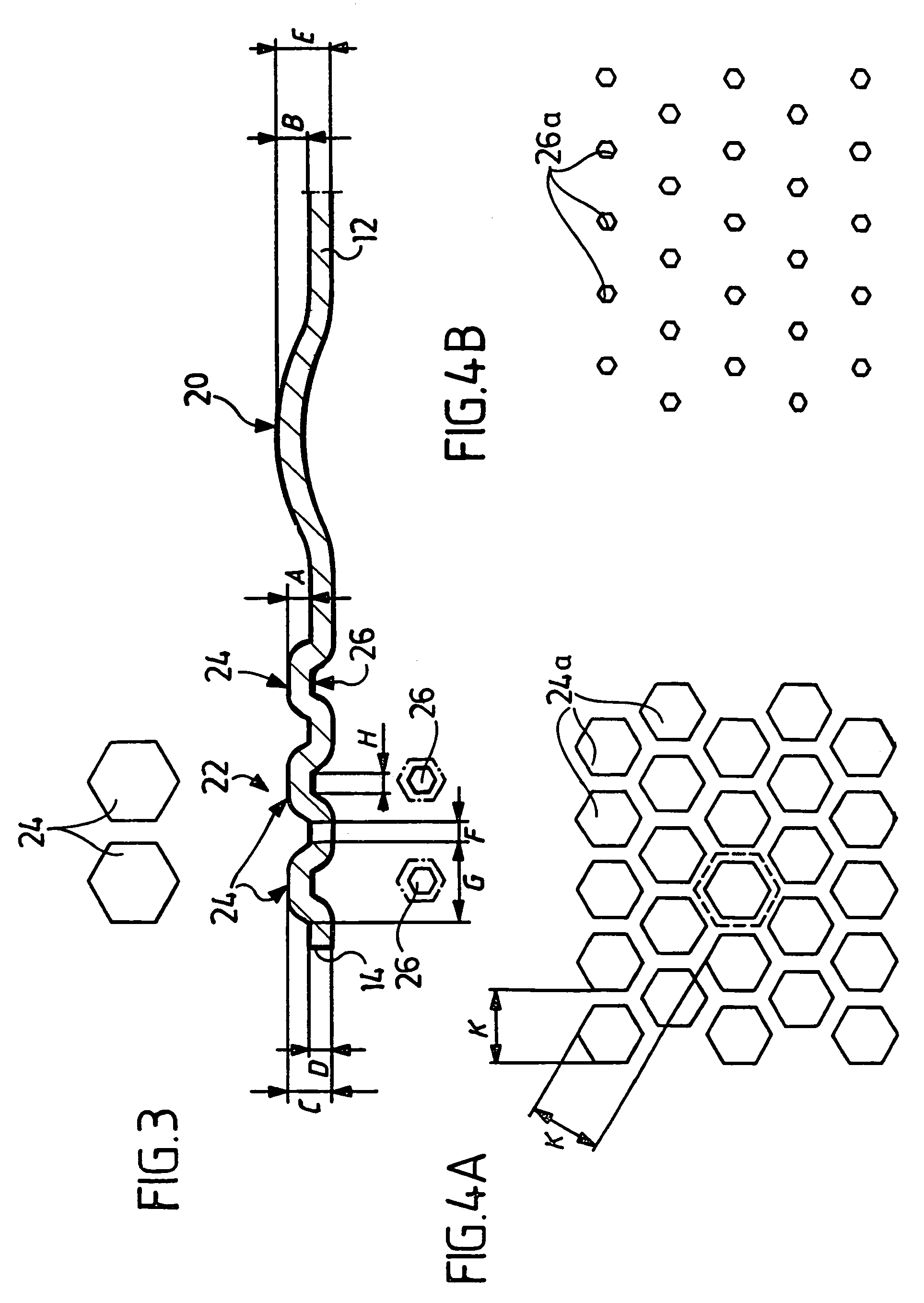
head gasket according to the invention, the elevations are approximately rectangular or trapezoidal in cross section and in a plan view of the sheet metal layer preferably border on one another with at least almost no spacing between them. The rectangular or trapezoidal shape of the elevations is preferably achieved by the elevations first being produced with a larger height than their
final height and then being flattened off somewhat by reverse deformation. This results in a higher stiffness of the elevations because the proportion of cold-worked zones and the degree of deformation of the sheet metal layer in the area of the elevations are increased.
[0021]The stopper is preferably produced on a so-called functional layer, i.e., on a
spring steel layer in which the bead mainly carrying out the sealing function also is or was produced. In the case of multilayer metallic cylinder head gaskets, however, the stopper can also be provided on another layer, as is disclosed in the prior art on cylinder head gaskets. In the case of a multilayer metallic cylinder
head gasket it is recommended not to provide the stopper on one of the outer
layers, but on a sheet metal layer
lying inside the stack of
layers, so as to eliminate the danger of the elevations pressing into the sealing surface of the engine block or the cylinder head, above all, when the cylinder head, as is customary in modern engines, is made of a
light metal alloy. It is also for this reason that elevations with flat crests are recommended.
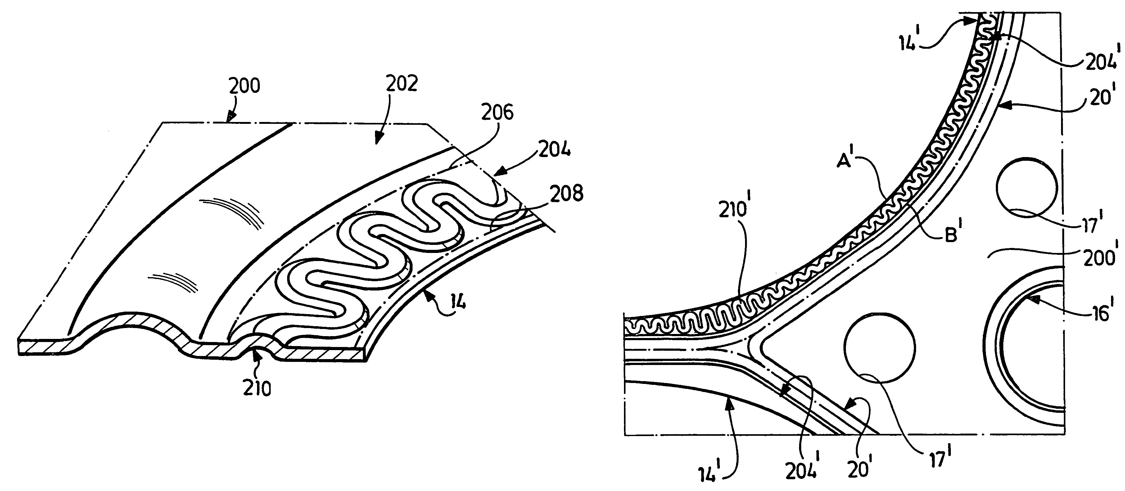
[0028]As mentioned above, in modern engines through-openings for cooling water, oil and the like are often located in the immediate vicinity of a combustion chamber, so that in areas around a combustion chamber opening in a cylinder
head gasket there is little space for accommodating a sealing bead and a stopper. The same applies to combustion chamber openings
lying close together. This can cause considerable difficulties in the above-described known cylinder head gaskets in which the stopper is formed not only by one but by several concentric beads. In this respect, the invention offers a further
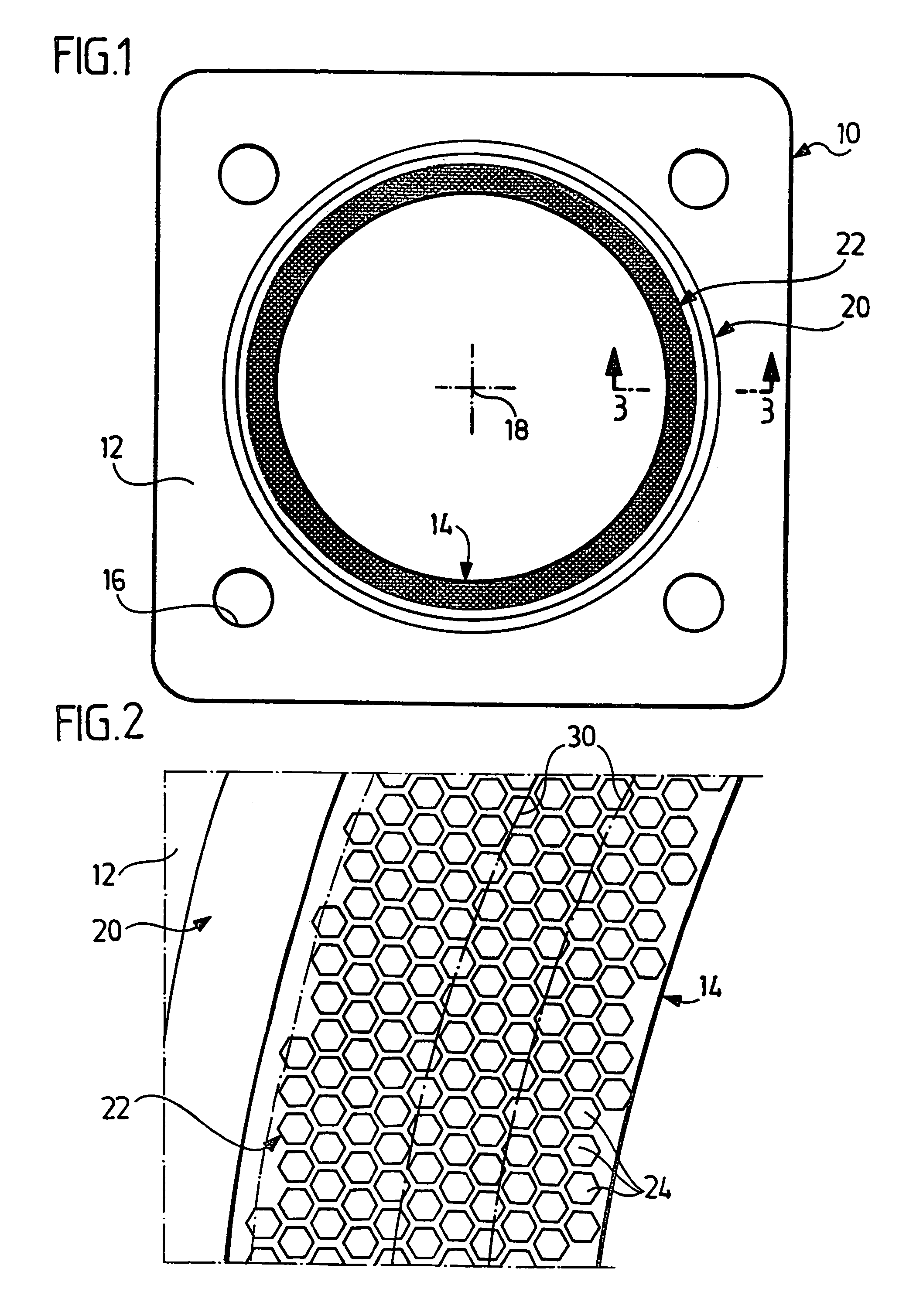
advantage when the stopper is formed by a pattern of small knob-like elevations, as it is then readily possible to provide a constricted portion of the knob pattern in such a narrow area of the cylinder head gasket. The ring-shaped band formed by the knob-like pattern can also be designed so as to be variable in its width, i.e., have a width profile, so as to take into account the fluctuations in the specific
surface pressure of the gasket around a combustion chamber. The same applies accordingly to embodiments with meandering beads or a ring of beads extending approximately radially.
[0029]In comparison with known stoppers consisting of one or several beads, which enclose the combustion chamber opening in the shape of a ring, the invention offers yet a further
advantage, in particular, when the stopper is formed by a pattern of knob-like elevations: A bead is supported on neighboring surfaces, on the one hand, only by its line-shaped crest and, on the other hand, only by its two line-shaped bead feet, whereas in a stopper according to the invention the pattern of the supporting surfaces is very much denser so that for this reason alone a stopper according to the invention can offer a much greater resistance to reverse deformation than a stopper consisting of one or several beads enclosing the combustion chamber opening in the shape of a ring.
[0031]In particularly advantageous embodiments of the invention, the stopper lies between the bead mainly carrying out the sealing function and the combustion chamber opening (in principle, the stopper or a further stopper could also lie radially outside the said bead), above all, because the bead mainly carrying out the sealing function is then better protected from the high temperatures prevailing in the combustion chamber.

