Digital amplifier apparatus and method of resetting a digital amplifier apparatus

a digital amplifier and digital amplifier technology, applied in the direction of amplifiers, dc amplifiers with modulators/demodulators, semiconductor devices/discharge tubes, etc., can solve the problems of large size and complex structure of digital amplifiers, and achieve the restriction of digital audio signal gain, simple configuration, and the effect of limiting the gain of digital audio signal

Active Publication Date: 2009-02-17
SONY CORP
View PDF3 Cites 2 Cited by
  • Summary
  • Abstract
  • Description
  • Claims
  • Application Information

AI Technical Summary

Benefits of technology

[0018]Hence, the gain of the digital audio signal is restricted, thereby stopping the superposing of the dither, when the abrupt receipt of a reset command is recognized while sound is being generated. A pulse-width modulated signal at an anacoustic level is thereby generated. Using this pulse-width modulated signal, the operation of the switching elements is terminated, stopping the supply of the drive current to the audio output. Thus, the audio output can be shifted from the sound-generating state to the anacoustic state without generating noise.
[0019]According to the present invention, the gain of the digital audio signal is restricted, thereby stopping the superposing of the dither, when the abrupt receipt of a reset command is recognized while sound is being generated. A pulse-width modulated signal at an anacoustic level is thereby generated. Then, using this pulse-width modulated signal, the operation of the switching elements is terminated, thereby stopping the supply of the drive current to the audio output. The audio output can therefore be shifted from the sound-generating state to the anacoustic state without generating noise. Hence, the invention can provide a digital amplifier apparatus and a method of resetting a digital amplifier apparatus, each capable of stopping an audio output without generating noise when a resetting operation is performed, by using a simple configuration with no additional circuits.

Problems solved by technology

The digital amplifier will inevitably be complex in structure and have a large size.

Method used


Image

  • Digital amplifier apparatus and method of resetting a digital amplifier apparatus
  • Digital amplifier apparatus and method of resetting a digital amplifier apparatus
  • Digital amplifier apparatus and method of resetting a digital amplifier apparatus

Examples


Embodiment Construction

[0029]An embodiment of the present invention will be described, with reference to the accompanying drawings.

(1) Configuration of the Digital Amplifier Apparatus

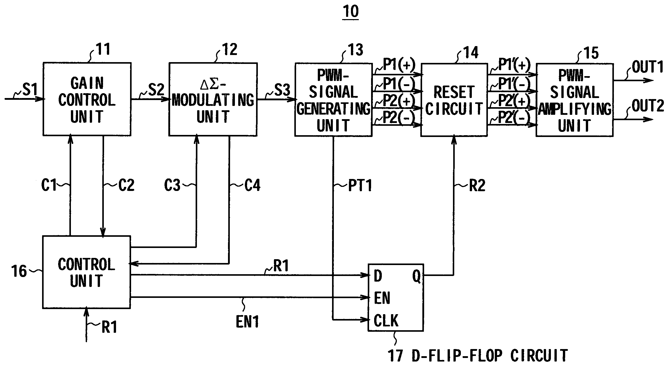
[0030]FIG. 4 shows a digital amplifier apparatus 10 according to an embodiment of this invention. A control unit 16 constituted by a Central Processing Unit (CPU) controls the other components of the apparatus 10. The apparatus 10 includes a gain control unit 11, a ΔΣ-modulating unit 12, a PWM-signal generating unit 13, a reset circuit 14, a PWM-signal amplifying unit 15, and a D-flip-flop circuit 17.

(1-1)Normal Mode

[0031]While the digital amplifier apparatus 10 is operating in the normal mode, a Pulse-Code Modulation (PCM) signal S1 reproduced from, for example, a Compact Disc (CD) is input to the gain control unit 11.

[0032]The gain control unit 11 performs gain adjustment, either amplifying or attenuating the PCM signal S1 to a predetermined level, generating a PCM signal S2. The PCM signal S2 is supplied to the ΔΣ-modulati...


PUM


Abstract

A digital amplifier apparatus includes a gain-adjusting section operable to adjust a gain of a digital audio signal; a dither-superposing section operable to superpose a predetermined dither on the digital audio signal; a pulse-width-modulated signal generating section operable to generate a pulse-width-modulated signal corresponding to the digital audio signal; an amplifying section operable to cause a switching element to perform a switching operation in accordance with the pulse-width-modulated signal; a pulse-width changing section operable to change a ratio between a “high” state and a “low” state of the pulse-width modulated signal; a synchronizing section operable to synchronize the pulse-width modulated signal with a reset signal that resets the digital audio signal; and a control section operable to perform a resetting operation by setting the gain of the digital audio signal to a zero level upon receiving the reset signal, stopping the superposing of the dither to thereby generate the pulse-width modulated signal, and setting the pulse-width modulated signal to the “low” state by using the pulse-width modulated signal synchronized with the reset signal, thereby causing the switching element to stop performing the switching operation.

Description

CROSS-REFERENCE TO RELATED APPLICATIONS[0001]The present application claims priority from Japanese Patent Application No. JP2005-380368 filed on Dec. 28, 2005, the disclosure of which is hereby incorporated by reference herein.BACKGROUND OF THE INVENTION[0002]1. Field of the Invention[0003]The present invention relates to a digital amplifier apparatus and a method of resetting a digital amplifier apparatus. The invention is suitable for application to digital amplifiers (D-class amplifiers) of, for example, Pulse-Width Modulation (PWM) type.[0004]2. Description of the Related Art[0005]Hitherto, with audio apparatuses incorporating a digital amplifier, the user may push the reset or mute button, thus performing a reset or mute operation, while the speaker is generating sound. Then, the speaker is forcedly stopped, ceasing to generate sound.[0006]At the time when the user performs the reset operation, the application of a gate voltage to the gate of the Metal Oxide Semiconductor-Field...

Claims


Application Information

Patent Timeline
Patent Type & Authority Patents(United States)
IPC IPC(8): H03F3/38
CPCH03F3/2173
Inventor MASUDA, TOSHIHIKOYAMAMOTO, YUSUKEMOROBOSHI, ARIHIRO
Owner SONY CORP
Why Eureka
Try Eureka