
Flexible shaft stabilizing devices with improved actuation

a stabilizer device and flexible shaft technology, applied in the field of surgical instruments, can solve the problems of inability to achieve the desired or necessary stiffness to hold the intended straight or curved position of the shaft, and the device is not without drawbacks, so as to improve the repeatability of positioning a rigid shaft, the effect of minimizing the permanent deformation of the tensioning element and improving the flexibility of the sha

Active Publication Date: 2009-03-03
ETHICON INC
View PDF14 Cites 15 Cited by
  • Summary
  • Abstract
  • Description
  • Claims
  • Application Information

AI Technical Summary

Benefits of technology

The present invention provides an improved design for a stabilizing device with a flexible shaft used in surgical tools. The invention addresses the problem of a marginally longer tensioning element when the shaft is in a straight position. The invention includes a tension element secured to a distal end of the flexible shaft and a cam positioned at the proximal end of the shaft to displace the tension element. A lever is operative to displace the cam, and elastic means interface between the tension element and the cam to displace the shaft as desired. The invention also provides an elastic means at the proximal end of the shaft to absorb the tension force applied to the tensioning element when the handle is actuated to lock the shaft in a rigid position. The invention also includes a terminal connector for holding a surgical tool apparatus to the distal end of the flexible shaft. The terminal connector provides rotational movement to the surgical tool according to the beating of the heart, or other movements of an organ the tool is attached to. The invention also provides a bendable suction stabilizer foot for use with the flexible shaft.

Problems solved by technology

These devices are not without drawbacks, however.
Among the drawbacks are difficulties with tensioning the fiber or cable that compresses the flexible shaft.
It has also been observed that after the first actuation of the shaft in such devices, subsequent actuations with equal turning of the actuator as the first actuation did not achieve the desired or necessary stiffness to hold the intended straight or curved position of the shaft.
Further, currently available shafts are often not conducive to convenient positioning of the distal end of the flexible shaft at the surgical site by the surgeon, even when the shaft is in the relaxed state.
Further, still detrimental wearing and gall can occur at the cam of the tensioning mechanism, including the generation of metal particulate that may compromise an otherwise sterile surgical field.
Turning of the handle to tension the fiber and position the shaft appropriately is also a time consuming and cumbersome task often requiring assistance from a second medical professional.
A great deal of force is typically required to actuate the handles of known flexible shaft devices having high shaft stiffness.
In addition to the drawbacks of known flexible shaft devices, a surgical apparatus secured to a distal end of a flexible shaft, or even a rigid retractor, may have its own drawbacks.
The former lack the ability to dynamically adapt to moving tissue, such as the beating heart, however, and rely instead on the resiliency of the material comprising the suction device to better conform to the targeted tissue.
The latter, on the other hand, are awkward, difficult to manipulate, and prone to user error.
Rigid devices cannot accommodate this curvature in the heart.
Moreover, is cumbersome to provide a suction line individually to each arm, however, as is commonly done in such devices.
Some devices in the prior art, including those sold under the OCTOPUS and ACROBAT brands, do not present a bendable bridge, and are therefore less able to adapt to the variety of tissue configurations a surgeon finds in practice.

Method used


Image

  • Flexible shaft stabilizing devices with improved actuation
  • Flexible shaft stabilizing devices with improved actuation
  • Flexible shaft stabilizing devices with improved actuation

Examples


Embodiment Construction

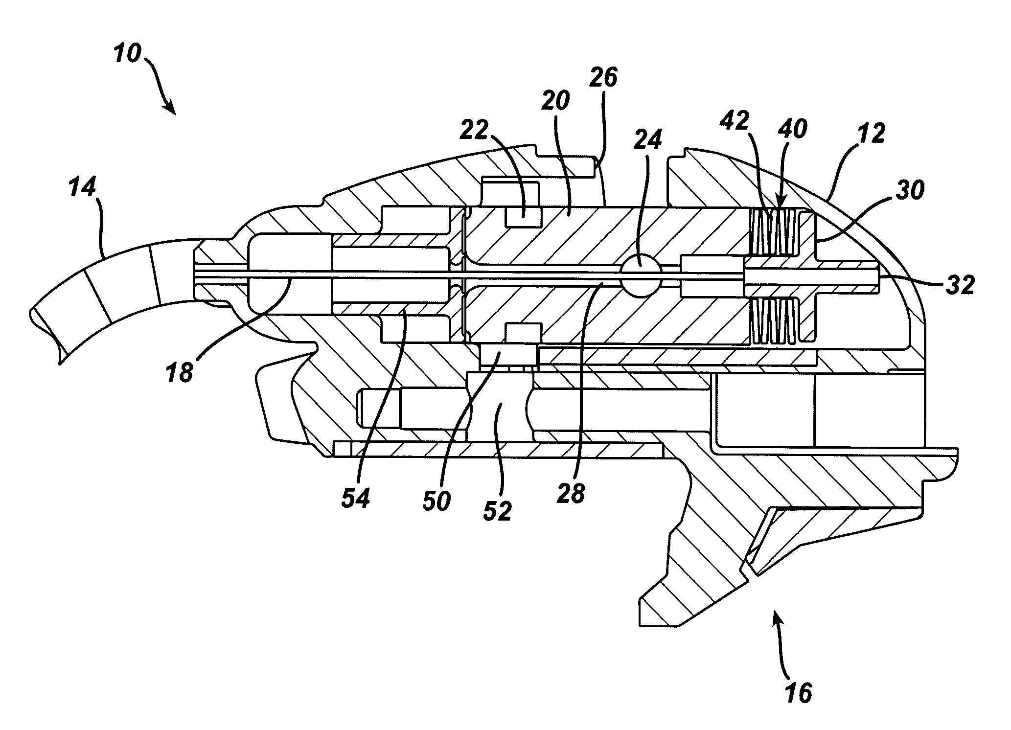
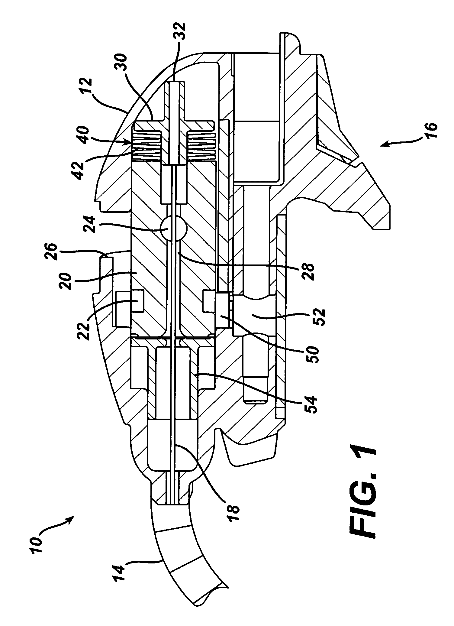
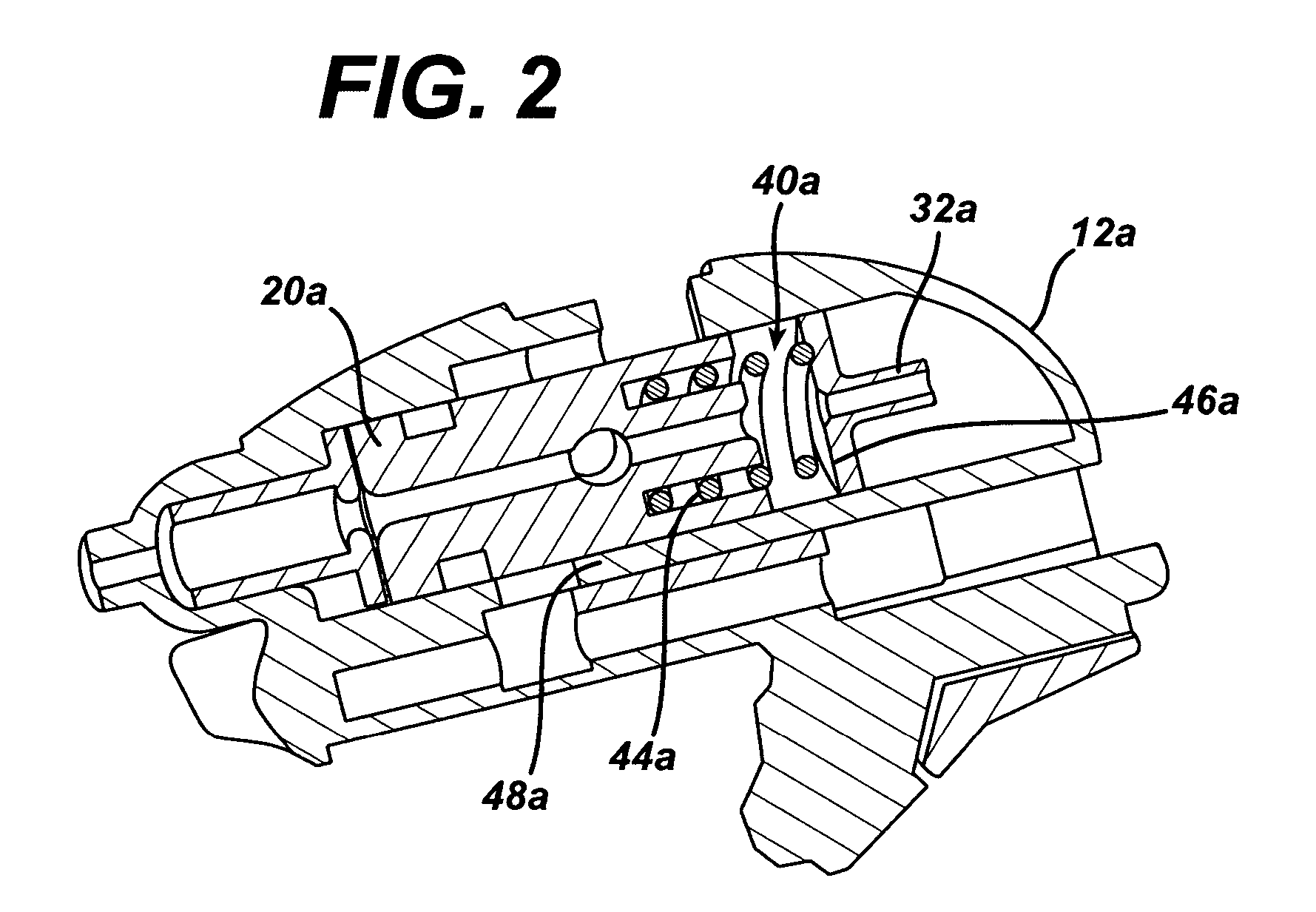
[0027]Experimentation has shown that for the certain shaft size and cam mechanism under test, using a wire-braided cable as a tension element, pre-loaded with 150 lbs of tension in a rigid straight configuration required 340 lbs. of tensile load to activate in a curved configuration. This additional loading exceeded the elastic limit of the cable, and stretched the cable by 0.06 in., which stretching degraded the shaft stiffness of subsequent activations. To accommodate for this, this invention provides an elastic means allowing compliance in the flexible shaft device without stretching the tension element.

[0028]Turning now to FIG. 1, shown is the proximal base 12 of the flexible shaft, generally 10. The shaft portion 14 extends distally from the proximal base 12. The proximal base 12 may include a mounting bracket 16, in this exemplary embodiment along an underside thereof. The mounting bracket 16 facilitates the use of the flexible shaft 10 in conjunction with a retractor, rib-spr...


PUM


Abstract

A stabilizing device having a flexible shaft with a terminal connector and surgical tools used therewith. The flexible shaft is responsive to a tension element connected to a distal end of the shaft and in communication with a proximal end of the shaft. An elastic means interfacing between the proximal end of the tension element and an actuating cam cause the shaft to adapt for differences in activating tension between straight and curved positions. Accordingly, stretching and deformation of the tensioning element is reduced and shaft stiffness upon activation of the tensioning element is repeatable. The terminal connector includes a ball-and-socket arrangement adapted to resiliently absorb movement of an organ during surgery. A bendable suction stabilizer foot adaptable to contours of an organ is also provided as an attachment to the stabilizer device.

Description

BACKGROUND OF THE INVENTION[0001]1. Field of Invention[0002]The invention relates to the field of surgical instruments, and more specifically to improvements in flexible shaft stabilizer devices and surgical tools usable in conjunction therewith.[0003]2. Description of Related Art[0004]In the field of medical instrumentation, flexible shaft stabilization devices are known in the art. Such devices are sold under the name OCTOPUS by the MEDTRONIC company and AXIUS by the GUIDANT company. Particularly in Coronary Artery Bypass Graft (CABG) procedures, such devices are used to stabilize the surface of the beating heart muscle at the site where an anastomosis will be formed. The devices commonly have a malleable shaft of a certain length, with a stabilizer foot or other apparatus at a distal end of the shaft. The apparatus is positioned as required, then a lead screw at a proximal end of the shaft is turned by some manner of handle to secure the shaft rigidly in place. The turning of the...

Claims


Application Information

Patent Timeline
Patent Type & Authority Patents(United States)
IPC IPC(8): A61F2/00
CPCA61B19/26A61B90/50
Inventor PARIHAR, SHAILENDRANGUYEN, STEVENMIKSZA, ANTHONYHART, JAMES C.GORDON, DAN
Owner ETHICON INC
Learn More