Integrity monitoring for geo-location systems

a geo-location system and integrity monitoring technology, applied in the field of wireless location systems, can solve the problems of failure isolation, inability to perform integrity monitoring, and large errors in gps receiver b>14/b> positioning solutions, and achieve the effect of enhancing integrity monitoring

Inactive Publication Date: 2009-03-03
SOUND VIEW INNOVATIONS
View PDF12 Cites 7 Cited by
  • Summary
  • Abstract
  • Description
  • Claims
  • Application Information

AI Technical Summary

Benefits of technology

[0018]The present invention is a method for performing integrity monitoring in the absence of redundant ranging measurements from a first ranging source type by using ranging measurements from a second ranging source type, wherein a ranging source type corresponds to a class of ranging sources and a rangi

Problems solved by technology

By contrast, poor quality PN phase offset measurements, such as outliers, result in GPS receiver 14 positioning solutions with large errors.
If p is not a vector, f

Method used


Image

  • Integrity monitoring for geo-location systems
  • Integrity monitoring for geo-location systems
  • Integrity monitoring for geo-location systems

Examples


first embodiment

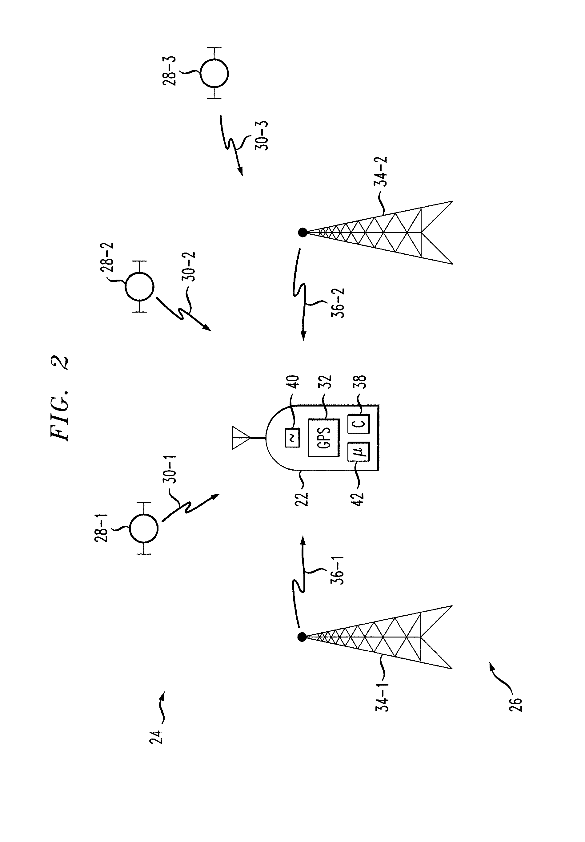
[0027]Wireless communication network 26 comprises a plurality of base stations 34-p, i.e., ranging source. Each base station 34-p transmits a signal 36-p that can be used by wireless terminal 22 or, with the assistance of wireless terminal 22, base station 34-p to obtain ranging information (e.g., to obtain round trip delay information). The ranging information can be indicated to wireless terminal 22 in a variety of forms. In a first embodiment, ranging information is indicated in the form pilot phase offsets, which correspond to measurements of code phases in pilot signals. In this embodiment, base stations 34-p are time synchronized and the pilot signals are transmitted at some known time relative to each other. For example, transmission of each pilot signal begins at the same time or at some known time apart. The transmitted pilot signals are detected and the pilot phase offsets are measured by wireless terminal 22, wherein the pilot phase offset measurements are used to obtain ...

second embodiment

[0028]In a second embodiment, ranging information is indicated in the form of signal strength. For example, base stations 34-p transmit signals 36-p, such as pilot signals, at a known transmission power. Signals 36-p are received and signal strengths measured by wireless terminal 22. Based on the known transmission power and the signal strength measurements, distances between base stations 34-p and wireless terminal 22 can be estimated, as is well-known in the art.

third embodiment

[0029]In a third embodiment, ranging information is indicated in the form of round trip delay (RTD) or one way delay (OWD) between base station 34-p and wireless terminal 22. In this embodiment, base stations 34-p may or may not be time synchronized with respect to each other and / or wireless terminal 22. The manners in which RTD and OWD may be determined are well-known in the art.


PUM


Abstract

Weighted ridge regression (WRR) processing is applied to three or more distance measurements to determine the location of a terminal. For example, in an integrated satellite-based navigation system/wireless network, the location of a mobile unit can be determined by applying WRR processing to at least three distance measurements, where one or more of the distance measurements are satellite-based distance measurements (e.g., GPS pseudorange measurements) and one or more are wireless network-based distance measurements (e.g., round-trip delay or pilot phase offset measurements). WRR processing provides improved accuracy in the determination of mobile unit position over conventional least mean square techniques.

Description

FIELD OF THE INVENTION[0001]The present invention relates generally to wireless communication systems and, in particular, to wireless location systems.BACKGROUND OF THE RELATED ART[0002]Satellite-based navigational systems provide accurate, two or three dimensional position information to worldwide users. FIG. 1 depicts a well-known satellite-based navigational system referred to as Global Positioning System (GPS) 10. GPS 10 comprises a plurality of satellites 12-j and at least one GPS receiver 14. Each satellite 12-j orbits earth at a known speed νj and is a known distance apart from other satellites 12-j. Each satellite 12-j transmits a GPS signal 11-j which includes a carrier signal with a known frequency f modulated using a unique pseudo-random noise (PN-j) code and navigational data (ND-j) associated with the particular satellite 12-j, wherein the PN-j code includes a unique sequence of PN chips and navigation data ND-j includes a satellite identifier, timing information and or...

Claims


Application Information

Patent Timeline
IPC IPC(8): H04W24/00G01S19/46G01S5/02G01S5/14
CPCG01S5/0268G01S19/46G01S19/42G01S19/20
Inventor DA, RENRICHTON, ROBERT ELLIS
Owner SOUND VIEW INNOVATIONS
Why Eureka
Try Eureka