Doped manganese dioxides

a technology of manganese dioxide and electrodes, which is applied in the field of batteries, can solve the problems that manganese dioxide is not generally employed in alkaline or lithium cells, and achieve the effect of improving electrochemical performan

Inactive Publication Date: 2009-03-10
ENERGIZER BRANDS
View PDF14 Cites 34 Cited by
  • Summary
  • Abstract
  • Description
  • Claims
  • Application Information

AI Technical Summary

Benefits of technology

[0006]The present invention, in one aspect, is a doped manganese dioxide (or XMD) useful as an active electrode material in both thin film and cylindrical batteries. The doped manganese dioxides provide several potential benefits, including improved electrochemical performance as compared with conventional manganese dioxides. The doped manganese dioxides of this invention comprise manganese, oxygen and at least one dopant deliberately incorporated into the atomic structure of the manganese dioxide.

Problems solved by technology

Because of its high impurity content, naturally occurring manganese dioxide is not generally employed in alkaline or lithium cells.

Method used


Image

  • Doped manganese dioxides
  • Doped manganese dioxides
  • Doped manganese dioxides

Examples


examples of emd manufacture

Example 1

Doped EMD; e.g., Mg2+ Doped EMD

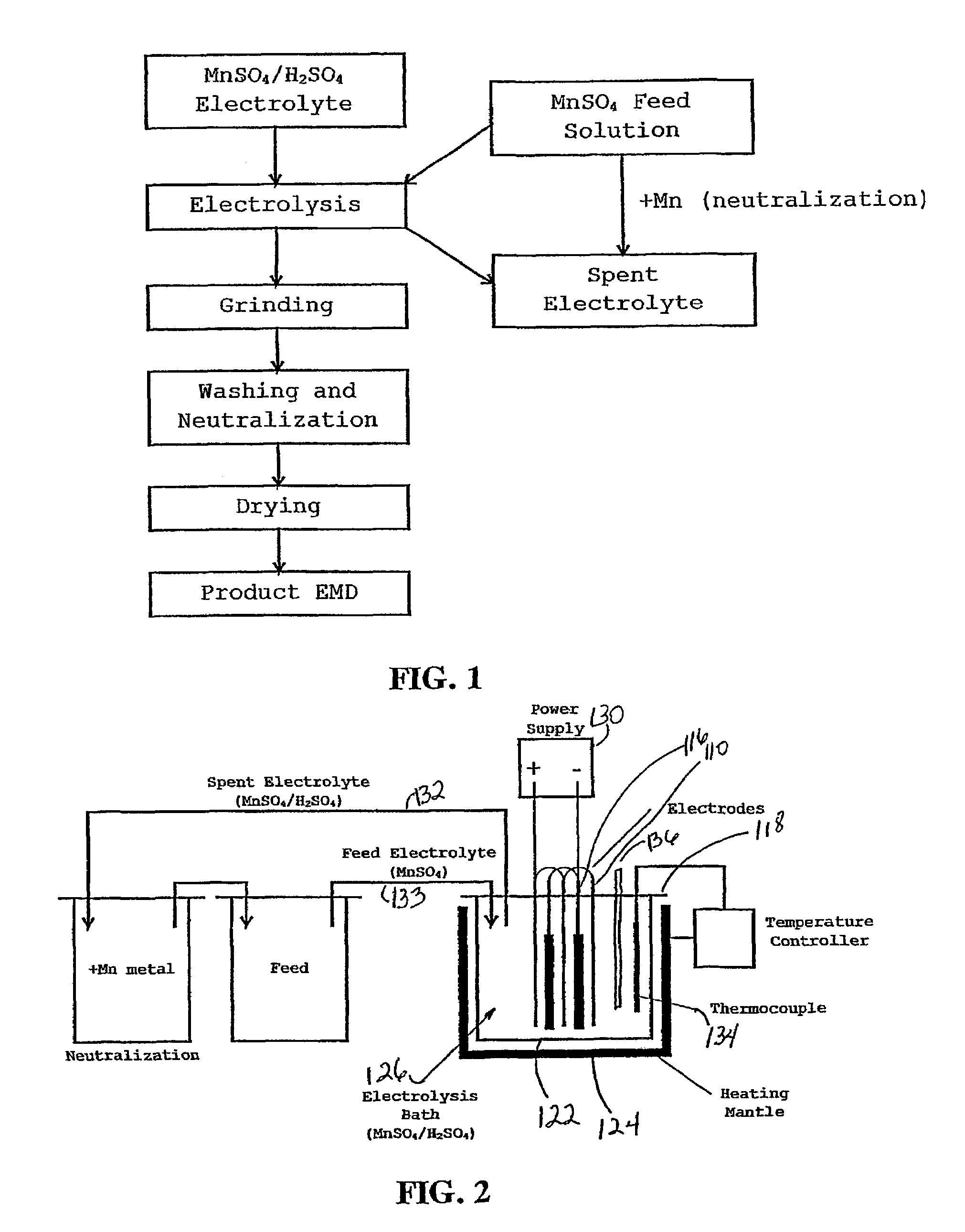
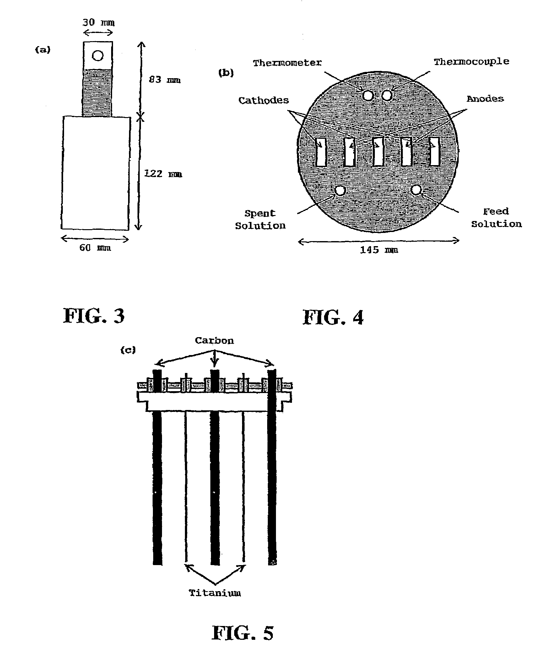
[0066]In this example the apparatus used was exactly the same as that described above and shown in FIGS. 2-5. Sufficient MgSO4 was added to the cell electrolyte (aqueous MnSO4 / H2 SO4) to make the concentration of Mg2+ 1000 ppm. Also, sufficient MgSO4 was added to the feed solution (aqueous MnSO4) to make the concentration of Mg2+ 1000 ppm. Electrolysis leading to XMD deposition was carried out as described previously.

example 2

Doped EMD; e.g., Mg2+ Doped EMD

[0067]This method is a more controlled alternative to that described in Example 1. The apparatus necessary for this example is similar to that used to prepare non-doped EMD, with the addition of another pump to be used for the addition of dopant to the electrolysis bath. Also necessary for this technique is a method for measuring the concentration of dopant in the electrolysis bath. Sufficient MgSO4 was added to the cell electrolyte prior to electrolysis to make the concentration of Mg2+ 5000 ppm. The feed solution was the same as that used when non-doped EMD was prepared. Another solution of 1000 ppm Mg2+ (from MgSO4) was also prepared. Electrolysis leading to XMD deposition was carried out similar to that described previously. The concentration of Mg2+ in the electrolysis bath was monitored continuously and fed back to the pump controlling MgSO4 solution addition. Based on the feedback information MgSO4 solution flow into the electrolysis cell was ei...

example 3

Doped EMD; e.g., Nb5+ Doped EMD (Nb(n-butoxide)5)

[0068]In this case NB2(SO4)5, or similar chloride or nitrate salt, was not available so an alternative approach had to be developed. The electrolysis cell was prepared as described previously and in Example 2, except that for this example no dopant was included in the electrolyte and the dopant solution contained 5000 ppm of Nb5+ (from Nb(n-butoxide)5) in methanol. This solution was pumped into the electrolysis cell just prior to electrolysis to raise the Nb5+ level in the electrolyte to 1000 ppm, and was continually added to the electrolysis bath after the onset of electrolysis to maintain 1000 ppm of Nb5+ in the cell. A benefit of this method of dopant introduction is that the methanol solvent evaporates immediately from the electrolysis cell (90-100° C.) leaving Nb5+ in solution. This technique was used for Ge4+, Nb5+ and Ti4+ dopant addition.


PUM

PropertyMeasurementUnit
weight percentaaaaaaaaaa
temperatureaaaaaaaaaa
temperaturesaaaaaaaaaa

Abstract

An active manganese dioxide electrode material that exhibits improved electrochemical performances compared with conventional manganese dioxide materials includes at least one dopant. The doped manganese dioxide electrode materials may be produced by a wet chemical method (CMD) or may be prepared electrolytically (EMD) using a solution containing manganese sulfate, sulfuric acid, and a dopant, wherein the dopant is present in an amount of at least about 25 ppm.

Description

FIELD OF THE INVENTION[0001]This invention relates to batteries and more particularly to battery electrodes comprised of manganese dioxide doped with at least one element.BACKGROUND OF THE INVENTION[0002]The Leclanchè cell, which uses an amalgamated zinc anode, an electrolyte of ammonium and zinc chloride dissolved in water, and a manganese dioxide cathode, was first introduced in the 1860s. Since then, manganese dioxide has been used extensively in primary, single-use battery cells and particularly in dry and alkaline manganese dioxide zinc cells. Manganese dioxide has also been employed in various rechargeable batteries, including non-aqueous electrolyte cells having an alkali light metal such as lithium as an active material.[0003]Battery grade manganese dioxide has been derived from naturally occurring manganese dioxide and synthetically produced manganese dioxide. Synthetic dioxide is generally divided into two categories: electrolytic manganese dioxide (EMD) and chemical manga...

Claims


Application Information

Patent Timeline
Patent Type & Authority Patents(United States)
IPC IPC(8): H01M4/50C01G45/02C01G45/12H01M2/02H01M4/04H01M4/24H01M4/52H01M4/525H01M6/40
CPCC01G45/02H01M2/0235H01M4/0438H01M4/049H01M4/24H01M4/50H01M4/525H01M6/40C01P2002/52C01P2002/54C01P2006/12C01P2006/40Y02E60/122Y02E60/124Y02E60/10H01M50/182
Inventor FEDDRIX, FRANK H.DONNE, SCOTT W.DEVENNEY, MARTINGORER, ALEXANDER
Owner ENERGIZER BRANDS
Why Eureka
Try Eureka