Charged particle beam emitting device and method for operating a charged particle beam emitting device

Active Publication Date: 2009-03-10
ICT INTEGRATED CIRCUIT TESTING GESELLSCHAFT FUER HALBLEITERPRUEFTECHNIK GMBH
View PDF16 Cites 15 Cited by
  • Summary
  • Abstract
  • Description
  • Claims
  • Application Information

AI Technical Summary

Benefits of technology

[0009]Typically, the emitting surface of the respective charged particle emitters should be separated with respect to each other to reduce or prevent mutual contamination by molecules desorbed during cleaning. The emitting surfaces of the respective charged particle beam guns are accommodated in separate vacuum chambers. Particularly, a transfer of molecules from the emitting surface being currently cleaned to the working emitting surface can thus be prevented. The charged particle beam guns can be formed as separate vacuum chambers accommodating its

Problems solved by technology

Although inspection and process diagnosis of intermediate structures allows the identification of defective semiconductor structures at a very early stage and hen

Method used


Image

  • Charged particle beam emitting device and method for operating a charged particle beam emitting device
  • Charged particle beam emitting device and method for operating a charged particle beam emitting device
  • Charged particle beam emitting device and method for operating a charged particle beam emitting device

Examples


Example

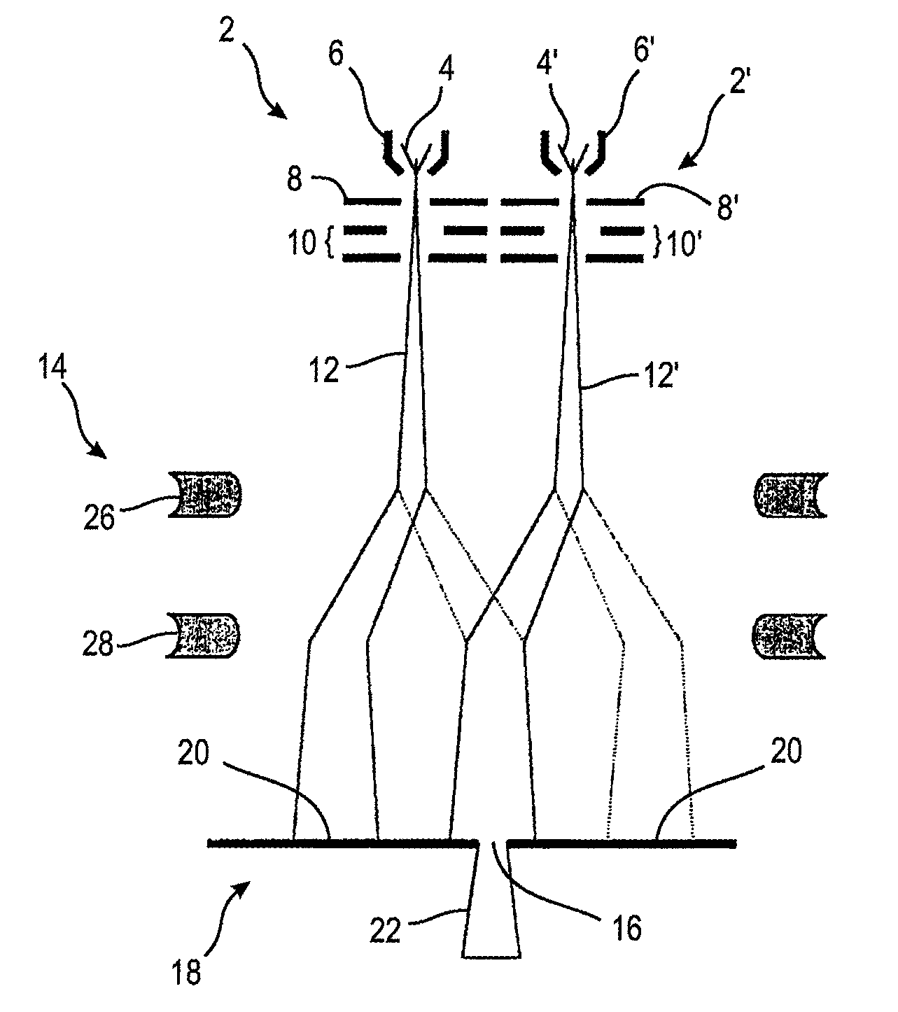
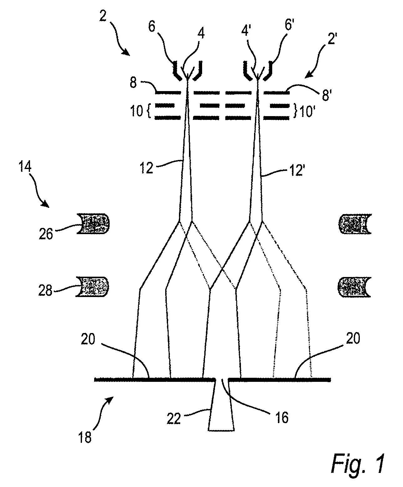
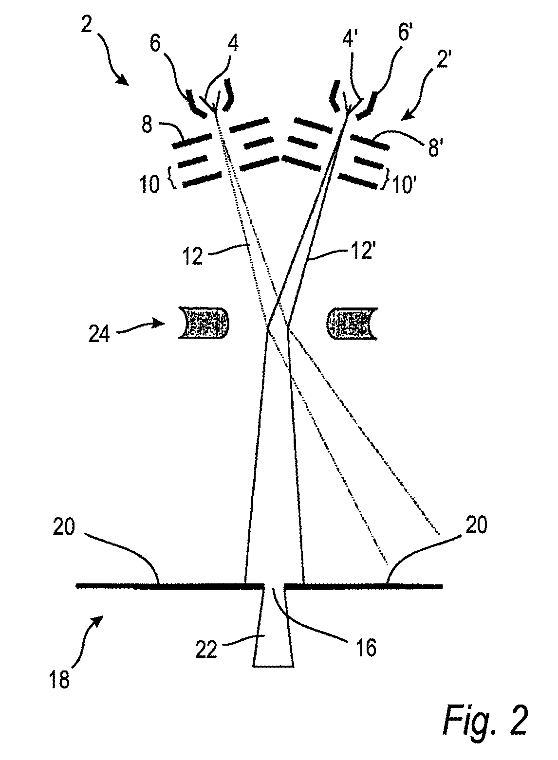
[0026]For high throughput applications such as wafer inspection and process diagnosis, which employ charged particle beams, any interruption of the inspection process should be kept to a minimum and, particularly, should be avoided. Among charged particle beam emitting devices, electron beam emitting devices and in particular cold field emitters play an increasingly important role due to their high brightness and small source size. Cold field emitters exhibit a typical emission characteristic which is mainly influenced by the absorption and desorption of residual gas molecules on the emitting surface. The adsorption of residual gas molecules results in a decrease of the emission current. Therefore, the emitting surface of a charged particle emitter needs to be decontaminated periodically. To this end, the charged particle beam emitting devices or apparatuses have been previously shut down and the emitting surface of the charged particle beam gun of the respective apparatus or device...


PUM


Abstract

A charged particle beam emitting device includes at least two charged particle beam guns, each of the at least two charged particle beam guns having a separate charged particle emitter with an emitting surface for emitting a respective charged particle beam. The charged particle beam emitting device further includes an aperture element comprising at least one aperture opening and a deflector unit. The deflector unit is adapted for alternatively directing the charged particle beams of the at least two charged particle beam guns on the at least one aperture opening so that, at the same time, one of the at least two charged particle beams is directed on the aperture opening while the respective other charged particle beam of the at least two charged particle beams is deflected from the aperture opening by the deflector unit. At the same time, only one of the two charged particle beam guns is used so that the temporarily unused charged particle beam gun can be subjected to a cleaning procedure. This ensures that the emitting surfaces of both charged particle beam guns can be alternatively and frequently cleaned with minimum interruption of the operation of the charged particle beam device.

Description

BACKGROUND OF THE INVENTION[0001]1. Field of the Invention[0002]The invention relates to improvements in the field of charged particle beam emitting devices and pertains particularly to a charged particle beam emitting device which includes at least two separate charged particle beam guns, and to a method for operating a charged particle beam emitting device.[0003]2. Description of the Related Art[0004]Advanced science and technology such as nanotechnology, biology and semiconductor industry places a high demand on charged particle beam emitting devices such as electron microscopes or electron beam writing devices with respect to reliability and performance. As an example, in semiconductor industry scanning electron microscopes are used for the inspection of manufactured semiconductor structures. The inspection is not restricted to the final semiconductor structure but also includes the inspection of intermediate manufacturing steps for the early identification of defective structur...

Claims


Application Information

Patent Timeline
IPC IPC(8): H01J37/10H01J37/147
CPCH01J3/06H01J9/505H01J37/067Y02W30/82
Inventor ZHOU, FANG
Owner ICT INTEGRATED CIRCUIT TESTING GESELLSCHAFT FUER HALBLEITERPRUEFTECHNIK GMBH
Why Eureka
Try Eureka