Switchable birdcage coil

a coil and switch technology, applied in the field of magnetic resonance imaging, can solve the problems of loss of sensitivity, reduced sensitivity during the receive mode, and dual coupling between the transmitter and the receiver coil

Inactive Publication Date: 2009-03-10
AGILENT TECH INC
View PDF8 Cites 28 Cited by
  • Summary
  • Abstract
  • Description
  • Claims
  • Application Information

AI Technical Summary

Benefits of technology

[0007]A birdcage coil of the present disclosure is used to produce the transmitter RF magnetic field over the sample and addresses the prior art problems by blocking essentially all residual currents that arise from any RF voltage that may be induced into its cells. The birdcage coil comprises a plurality of identical cells connected there between in a ladder pattern. Each cell has an upper ring reactive element, a lower ring reactive element, and a leg reacti

Problems solved by technology

Residual coupling between the transmitter and receiver coils reduces the sensitivity during the receive mode.
The small NMR currents in the receiver coil windings induce currents in the transmitter coil windings causing a loss in sensitivity since the power is absorbed and not av

Method used


Image

  • Switchable birdcage coil
  • Switchable birdcage coil
  • Switchable birdcage coil

Examples


Embodiment Construction

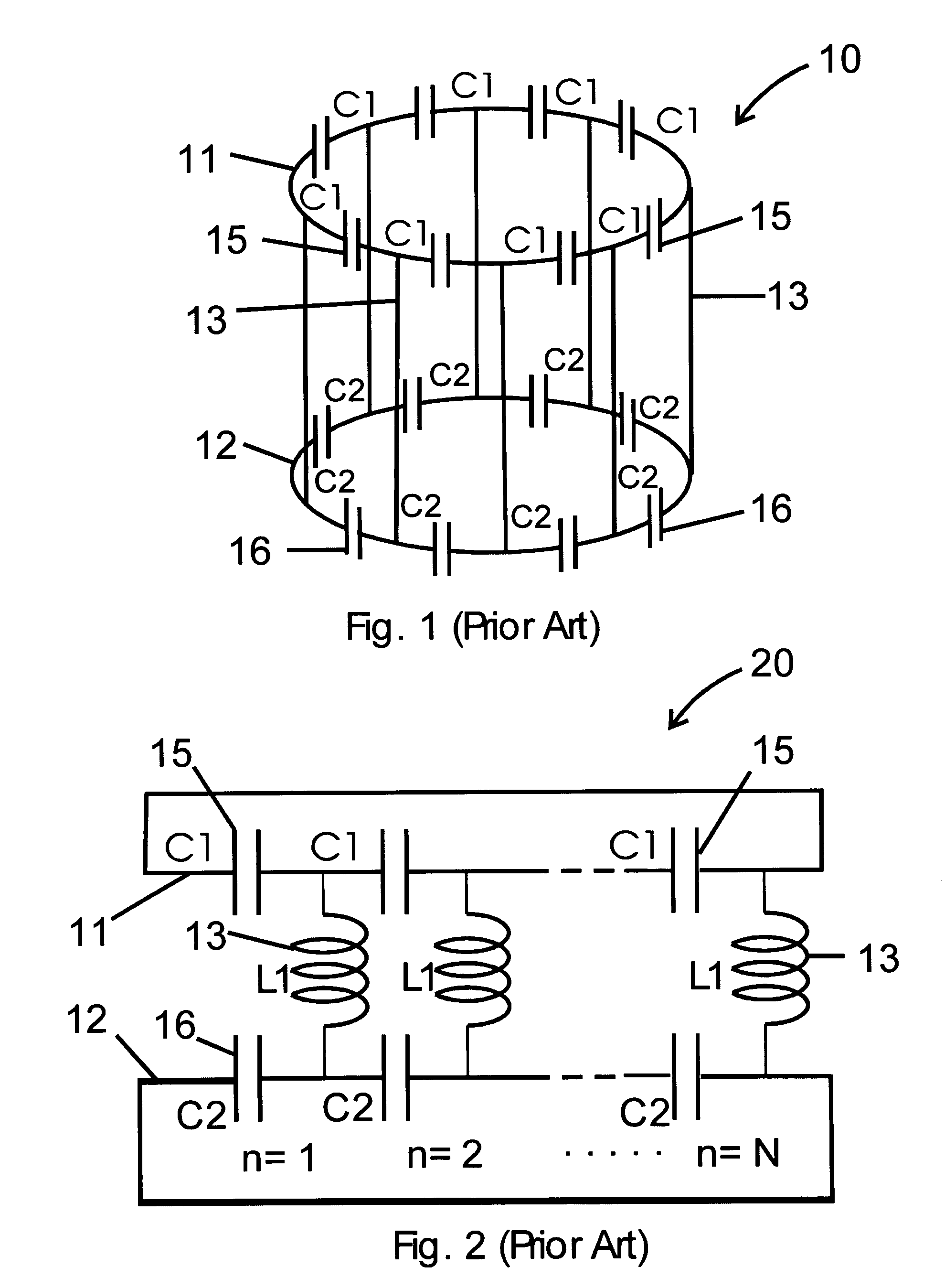
[0017]Turning toward the drawings, FIG. 1 is a diagram of a prior art high-pass birdcage coil. Birdcage coil 10 comprises upper ring 11 and lower ring 12, each with N equally spaced capacitors around a respective ring. Upper ring capacitors 15, each has a capacitance value C1, and the low ring capacitors16, each has a capacitance value C2. Leg inductors 13 have an inductance value L1 and are extended between each pair of the upper ring capacitors and a corresponding pair of the low ring capacitors. The birdcage coil is formed as a linear network of cells. In each cell an upper ring capacitor 15 is connected to one end of a leg inductor 13, and a low ring capacitor 16 is connected to the other end of the same leg inductor 13. These elements are coupled together to form an electrical network 20 as illustrated in FIG. 2. The birdcage coil is resonant at frequencies where the total phase shift of currents around the network combine constructively, i.e. where the total phase shift around...


PUM


Abstract

A switchable birdcage coil functioning as a transmitter coil and a separate RF surface coil functioning as the receiver coil are utilize in NMR and MRI apparatus. To prevent the switchable birdcage coil from absorbing energy by coupling to the receiver coil or by absorbing power from the RF field produced by the precessing nuclear spins, one or more of the reactive elements of the birdcage coil are switched from a normal reactive impedance state to a high impedance state. The high impedance state is formed by switchably combining the reactive element with a complementary reactive element thereby forming parallel resonant high impedance circuit that is tuned to resonate at the NMR frequency.

Description

FIELD OF THE INVENTION[0001]The invention is in the field of magnetic resonance imaging (MRI) using nuclear magnetic resonance (NMR) phenomenon and relates to the use of an actively switchable birdcage coil providing better signal-to-noise ratio.BACKGROUND OF THE INVENTION[0002]Birdcage coils are commonly used in NMR and MRI instrumentation to produce the RF field over the sample or the object being imaged. The birdcage coils are described, for example, in the U.S. Pat. Nos. 4,689,548 and 4,694,255. The conventional birdcage coil consists of a number of evenly spaced leg conductive elements interconnecting a pair of ring conductive elements. Each conductive element includes at least one reactive element that may be a capacitive or inductive element. There are two basic designs of birdcage coils: high-pass birdcage coils having inductive leg elements and capacitive ring elements, and low-pass birdcage coils having capacitive leg elements and inductive ring elements. There are also “b...

Claims


Application Information

Patent Timeline
IPC IPC(8): G01V3/00
CPCG01R33/34046G01R33/34076G01R33/3657
Inventor WONG, WAI HARATH, ALAN R.SUDDARTH, STEVEN A.
Owner AGILENT TECH INC
Why Eureka
Try Eureka