
Method and apparatus for gasifying carbonaceous material

Inactive Publication Date: 2009-03-17
FOSTER WHEELER ENERGIA OY
View PDF10 Cites 10 Cited by
  • Summary
  • Abstract
  • Description
  • Claims
  • Application Information

AI Technical Summary

Benefits of technology

[0012]An object of the present invention is to provide a method and an apparatus that improves the usability of a gasification system for carbonaceous material.
[0013]It is especially an object of the present invention to provide a simple method and apparatus for avoiding problems caused by tar compounds entrained with the product gas.
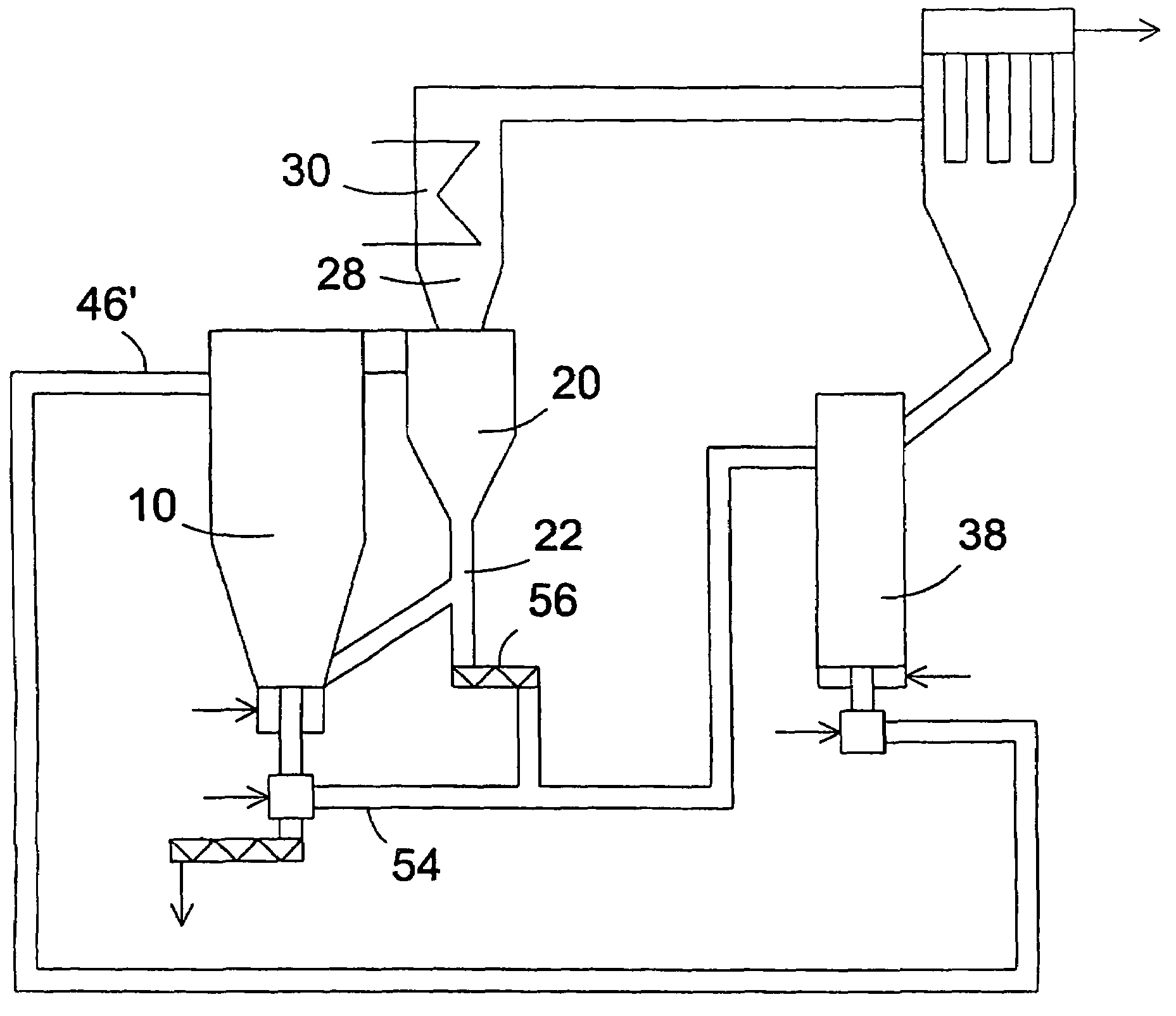
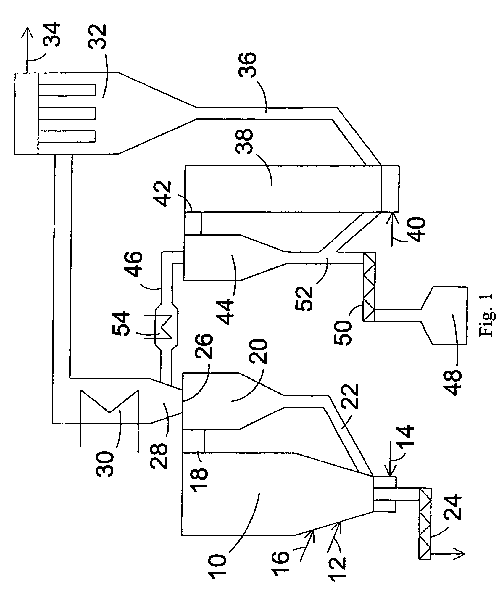
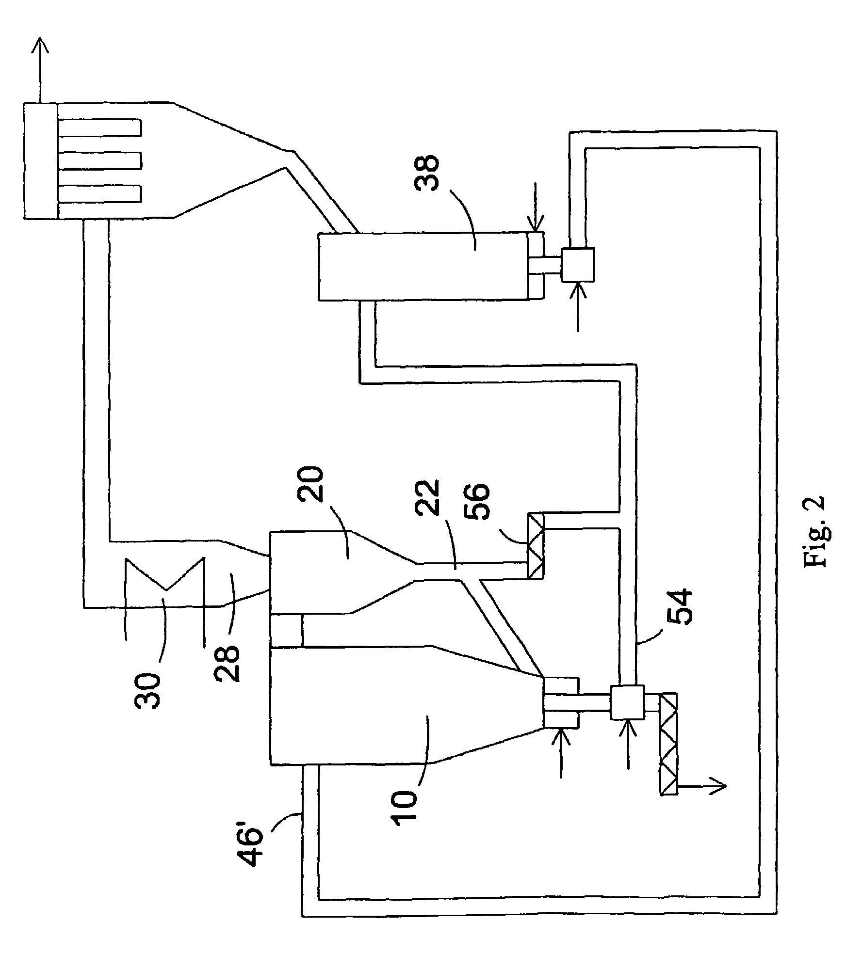
[0014]To solve these problems, a method is provided, wherein ash particles are guided from an ash reactor along a conveying duct to a gas cooler or to a location upstream of the gas cooler, thereby increasing the ash content of the product gas and reducing the amount of condensing tar compounds sticking to the heat exchange surfaces of the gas cooler.

Problems solved by technology

The gasification temperature, especially with fluidized bed gasifiers, is often relatively low, e.g., 500-1000° C., such that the non-gasified carbon may significantly reduce the gas production level of the gasifier.
Since particle filters for gas operating at a high temperature are expensive and are prone to be damaged, the product gas is usually cooled prior to filtering.
The condensed tar compounds may, for example, form deposits on the heat exchange surfaces of the gas cooler and on the filter, which are difficult to remove.
Thus, the tar compounds decrease the heat exchange capacity of the heat exchange surfaces and clog filtering elements of the filter, thereby increasing the pressure loss caused by the filter.
The fly ash and bottom ash of the gasification reactor may also contain PAH compounds and other carbon compounds harmful to the environment.

Method used


Image

  • Method and apparatus for gasifying carbonaceous material
  • Method and apparatus for gasifying carbonaceous material
  • Method and apparatus for gasifying carbonaceous material

Examples


Embodiment Construction

[0033]A gasification reactor 10 is disclosed in FIG. 1 as a circulating fluidized bed gasifier, but it might also be another type of a reactor suitable for gasifying fuel containing carbonaceous material. A material to be gasified, an inert bed material (e.g., sand), and, if necessary, a sorbent (e.g., lime stone), are supplied to the reactor 10 by feeding means 12.

[0034]Gasification gas, which acts as fluidizing gas, is introduced to the bottom of the gasifier by feeding means 14. The gasification gas may be air and / or oxygen, and possibly steam. Secondary gasification gas may be supplied to the fluidized bed of the gasifier by means 16. The fluidizing gases and the product gases generated in the reactor entrain therewith solid particles from the circulating fluidized bed reactor and carry them to the upper part of the reactor 10. In the upper part of the reactor, a portion of the solid material exits with the product gas through an outlet opening 18 to a particle separator 20. The...


PUM


Abstract

A method and an apparatus for gasifying carbonaceous material, in which (a) gasifying carbonaceous material is gasified in a gasification reactor of a gasification system to produce a product gas, (b) the product gas, ash particles entrained with the product gas, residual carbon, and gasified tar compounds are discharged from the gasification reactor to a product gas channel, (c) the product gas discharged from the gasification reactor is cooled using a gas cooler disposed along the product gas channel, so that the tar compounds are condensed to a liquid from that tends to stick to heat exchange surfaces of the gas cooler, (d) solid material including the ash particles and the residual carbon is separated from the gasification system, (e) the solid material separated from the gasification system is guided to an ash reactor, and oxygen-containing gas is supplied to the ash reactor, whereby the residual carbon in the solid material reacts with oxygen, and additional ash particles and exhaust gas are generated, and (f) ash particles from the ash reactor are guided along a conveying duct to the gas cooler or to a location upstream of the gas cooler, thereby increasing the ash content of the product gas and decreasing the tendency of the condensed tar compounds to stick to the heat exchange surfaces of the gas cooler.

Description

BACKGROUND OF THE INVENTION [0001]The present invention relates to a method and an apparatus for gasifying carbonaceous material.[0002]More particularly, the present invention relates to a method of gasifying carbonaceous material, in which carbonaceous material is gasified to produce a product gas in a gasification reactor of a gasification system. The product gas and ash entrained therewith, residual carbon, and gaseous tar compounds are discharged from the gasification reactor to a product gas channel. There, the product gas is cooled in a gas cooler, whereby the tar compounds condense into a liquid form, which tends to stick on surfaces. Solid material containing ash particles and residual carbon is separated from the gasification system and guided to an ash reactor. Oxygen-containing gas is supplied to the ash reactor, whereby the residual carbon reacts with oxygen to generate ash particles and exhaust gas.[0003]The invention also relates to an apparatus for gasifying carbonace...

Claims


Application Information

Patent Timeline
IPC IPC(8): B01J7/00B01J8/18C01B3/36C10J3/46C10J3/54F27B15/00F27B15/08H01M8/06C10J3/56
CPCC10J3/482C10J3/56C10J2300/0956C10J2300/0959C10J2300/0973C10J2300/0983C10J2300/1637C10J2300/1884
Inventor HILTUNEN, MATTINIEMINEN, LEGAL REPRESENTATIVE, KATRIINANIEMINEN, JORMA
Owner FOSTER WHEELER ENERGIA OY
Learn More