Anode holder

a technology of anode and holder, which is applied in the direction of machining electrodes, electrical-based machining electrodes, manufacturing tools, etc., can solve the problems of proportional wear of anodes to the amount of plating, and achieve good electrical connection and maintain corrosion resistance.

Active Publication Date: 2009-03-24
EBARA CORP
View PDF4 Cites 5 Cited by
  • Summary
  • Abstract
  • Description
  • Claims
  • Application Information

AI Technical Summary

Benefits of technology

[0008]The present invention has been made in view of the above drawbacks. It is, therefore, an object of the present invention to provide an anode holder which can maintain a corrosion resistance of a conductive portion between an anode and a power source and provide a good electrical connection between the conductive portion and the anode.
[0009]According to a first aspect of the present invention, there is provided an anode holder which can maintain a corrosion resistance of a conductive portion between an anode and a power source and provide a good electrical connection between the conductive portion and the anode. The anode holder is used to hold an anode in a plating tank. The anode holder includes a bar having a conductive portion connected to a power source, a conductive anode shaft attached to the bar, and an anode connected to the conductive anode shaft. The conductive anode shaft includes an external thread portion provided at an end of the conductive anode shaft, an O-ring, and a step portion provided between the O-ring and the external thread portion. The step portion has a diameter larger than a diameter of the external thread portion but smaller than a diameter of the O-ring. The anode includes an internal thread hole to which the external thread portion of the conductive anode shaft is screwed. The anode also includes a receiving portion for receiving the step portion of the conductive anode shaft in a state such that the O-ring of the conductive anode shaft is brought into contact with an inner surface of the receiving portion.
[0010]According to a second aspect of the present invention, there is provided an anode which can maintain a corrosion resistance of a conductive portion between the anode and a power source and provide a good electrical connection between the conductive portion and the anode. The anode is held in a plating tank by an anode holder. The anode includes an internal thread hole to which an external thread portion provided at an end of a conductive anode shaft is screwed. The anode also includes a receiving portion for receiving a step portion of the conductive anode shaft between the external thread portion and an O-ring of the conductive anode shaft in a state such that the O-ring is brought into contact with an inner surface of the receiving portion. The step portion has a diameter larger than a diameter of the external thread portion but smaller than a diameter of the O-ring.
[0011]According to a third aspect of the present invention, there is provided a conductive anode shaft which can maintain a corrosion resistance of a conductive portion between an anode and a power source and provide a good electrical connection between the conductive portion and the anode. The conductive anode shaft connects an anode held in a plating tank and a bar connected to a power source. The conductive anode shaft includes an external thread portion provided at an end of the conductive anode shaft. The external thread portion is screwed to an internal thread hole formed in an anode. The conductive anode shaft also includes an O-ring and a step portion provided between the O-ring and the external thread portion. The step portion has a diameter larger than a diameter of the external thread portion but smaller than a diameter of the O-ring. The step portion is received in a receiving portion formed in the anode in a state such that the O-ring is brought into contact with an inner surface of the receiving portion.

Problems solved by technology

Thus, the anode is worn in proportion to the amount of plating.

Method used


Image

  • Anode holder
  • Anode holder
  • Anode holder

Examples


Embodiment Construction

[0021]A plating apparatus having an anode holder according to an embodiment of the present invention will be described below with reference to FIGS. 1 through 8. Like or corresponding parts are denoted by like or corresponding reference numerals throughout the drawings, and will not be described below repetitively.

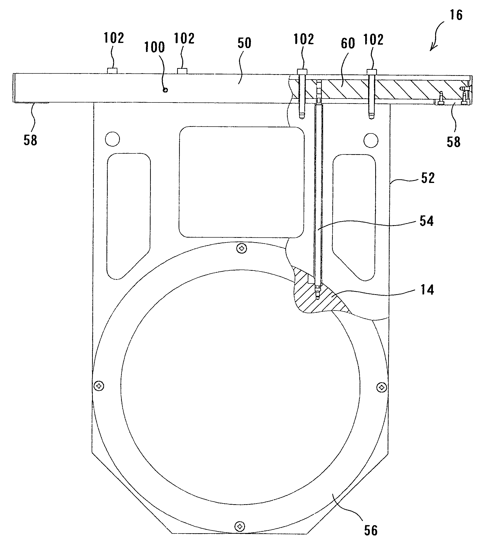
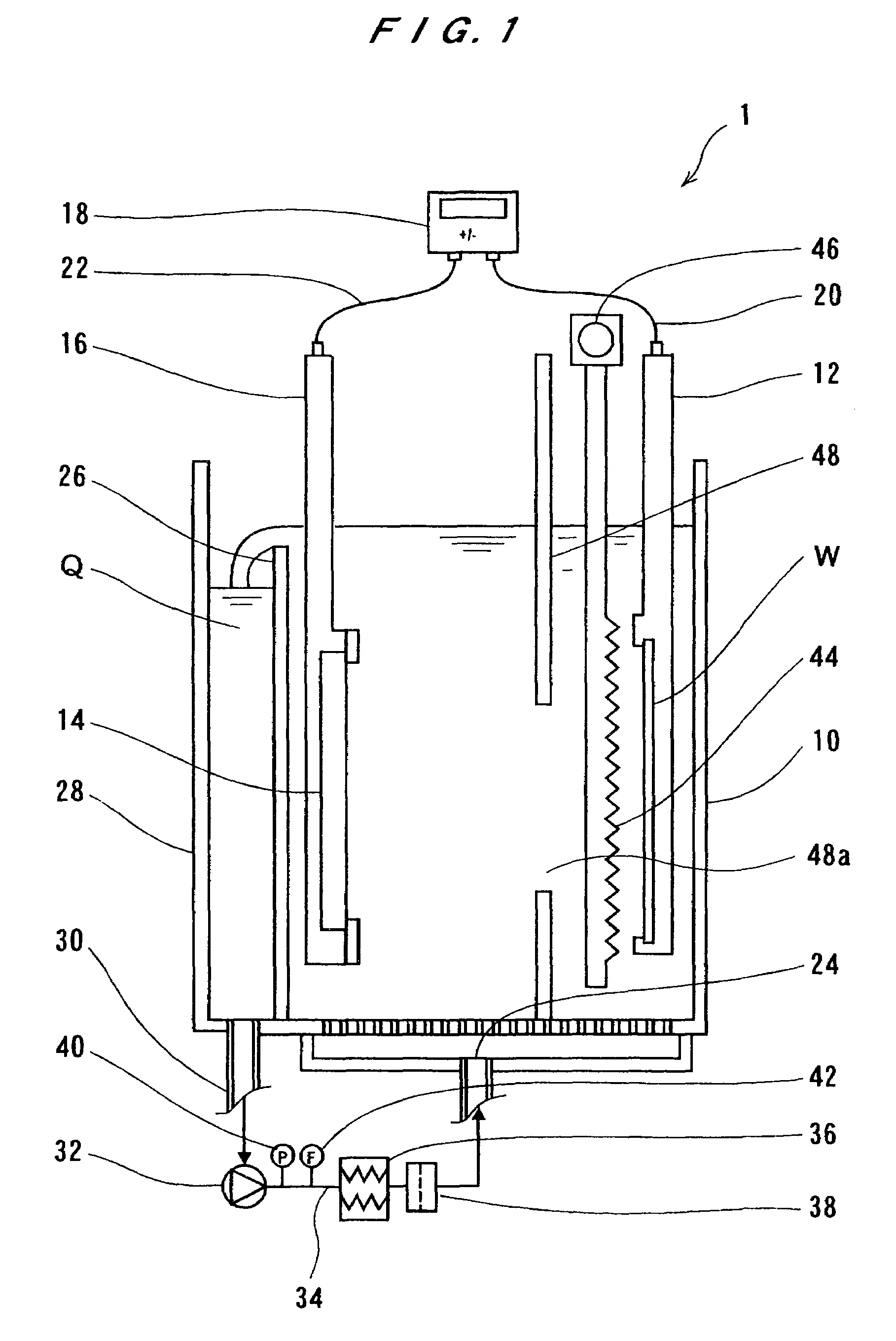
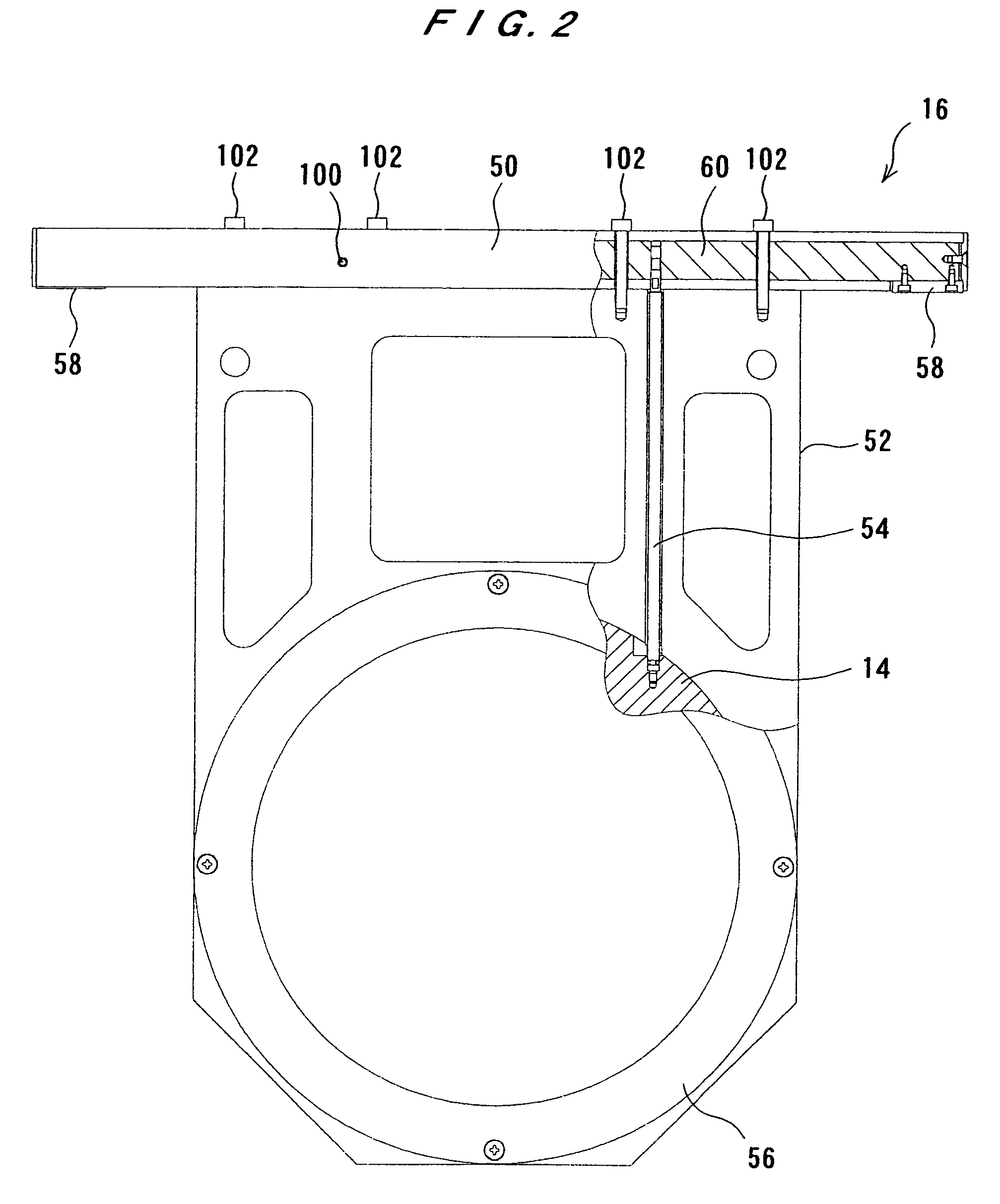
[0022]FIG. 1 is a schematic view showing a plating apparatus 1 having an anode holder according to an embodiment of the present invention. As shown in FIG. 1, the plating apparatus 1 has a plating tank 10 for holding a plating solution Q therein, a substrate holder 12 for holding a substrate W, an anode holder 16 for holding an anode 14, and a plating power source 18. The anode 14 is disposed in the anode holder 16 so as to face the substrate W.

[0023]The substrate W and the anode 14 are disposed in a vertical direction and immersed in the plating solution Q held by the plating tank 10. The substrate W and the anode 14 are disposed in parallel to each other so that a surfac...


PUM

PropertyMeasurementUnit
thicknessaaaaaaaaaa
conductiveaaaaaaaaaa
diameteraaaaaaaaaa

Abstract

An anode holder is used to hold an anode in a plating tank. The anode holder includes a bar having a conductive portion connected to a power source, a conductive anode shaft attached to the bar, and an anode connected to the conductive anode shaft. The conductive anode shaft includes an external thread portion provided at an end of the conductive anode shaft, an O-ring, and a step portion provided between the O-ring and the external thread portion. The step portion has a diameter larger than a diameter of the external thread portion but smaller than a diameter of the O-ring. The anode includes an internal thread hole to which the external thread portion of the conductive anode shaft is screwed. The anode also includes a receiving portion for receiving the step portion of the conductive anode shaft in a state such that the O-ring of the conductive anode shaft is brought into contact with an inner surface of the receiving portion.

Description

BACKGROUND OF THE INVENTION[0001]1. Field of the Invention[0002]The present invention relates to an anode holder, and more particularly to an anode holder for holding an anode in a plating tank used for forming a metal film or an interconnection on a large-scale integrated circuit (LSI) substrate.[0003]2. Description of the Related Art[0004]Recently, a plating process has been employed to form metal films, organic films, interconnections, or bumps (protruding connecting electrode terminals) for semiconductor circuits in a substrate such as a silicon wafer. For example, it has widely been practiced to form bumps of gold, silver, copper, solder, nickel, or multi-layer materials of these metals at predetermined portions on a surface of a semiconductor wafer, which has semiconductor circuits and fine interconnections between the semiconductor circuits, to electrically connect the interconnections via the bumps to electrodes of a package substrate or to tape automated bonding (TAB) elect...

Claims


Application Information

Patent Timeline
Patent Type & Authority Patents(United States)
IPC IPC(8): C25B9/02
CPCC25D17/10C25D17/12
Inventor KURIYAMA, FUMIOKIMURA, MASAAKI
Owner EBARA CORP
Why Eureka
Try Eureka