GaN based digital controlled broadband MMIC power amplifier

a broadband mmic power amplifier and digital control technology, applied in amplifiers, amplifiers with semiconductor devices/discharge tubes, amplifiers with coupling networks, etc., can solve the problems of large gain variation, linear degradation, and distortion of output signals of fet based distributed high power amplifiers

Active Publication Date: 2009-03-24
ROCKWELL COLLINS INC
View PDF3 Cites 30 Cited by
  • Summary
  • Abstract
  • Description
  • Claims
  • Application Information

AI Technical Summary

Benefits of technology

[0006]According to a first embodiment, a broadband MMIC power amplifier is disclosed. Power amplifier comprises a distributed pre-driver, further comprising a digital variable attenuator, and a distributed high power amplifier (HPA). Power amplifier also comprises an integrated coupler and detector unit. Pre-driver may be digital and may be suitable for providing extended signal linearity. Power amplifier further comprises a feedback control loop. Feedback control loop comprises an on-chip coupler and voltage detector and is configured to provide a voltage reference to the pre-driver.

Problems solved by technology

FET based distributed high power amplifiers suffer from large gain variation due to leakage and low early voltage.
Such gain variations and leakage may cause degraded linearity and distorted output signals.

Method used


Image

  • GaN based digital controlled broadband MMIC power amplifier
  • GaN based digital controlled broadband MMIC power amplifier
  • GaN based digital controlled broadband MMIC power amplifier

Examples


Embodiment Construction

[0018]Reference will now be made in detail to presently preferred embodiments of the invention, examples of which are illustrated in the accompanying drawings.

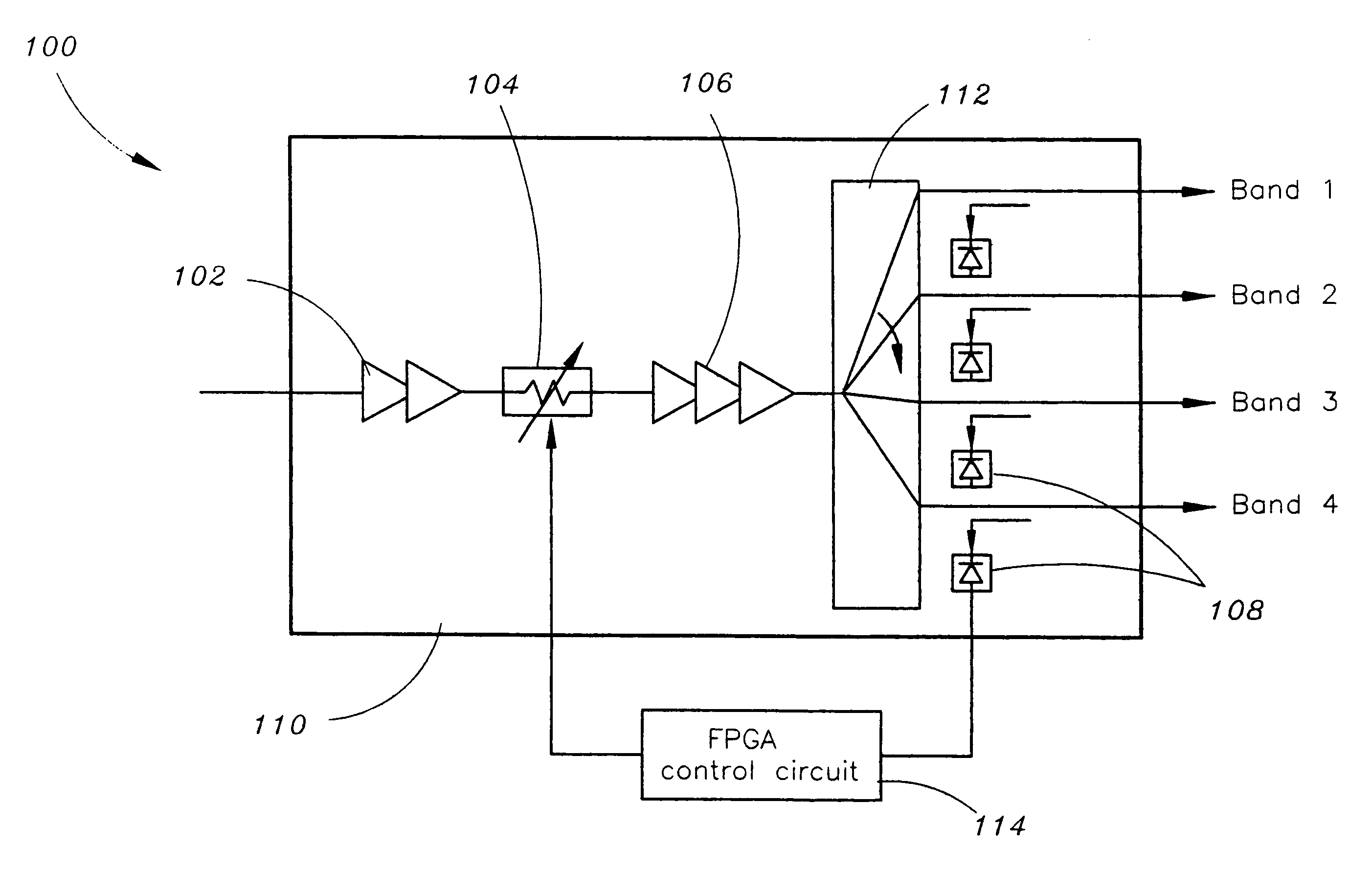
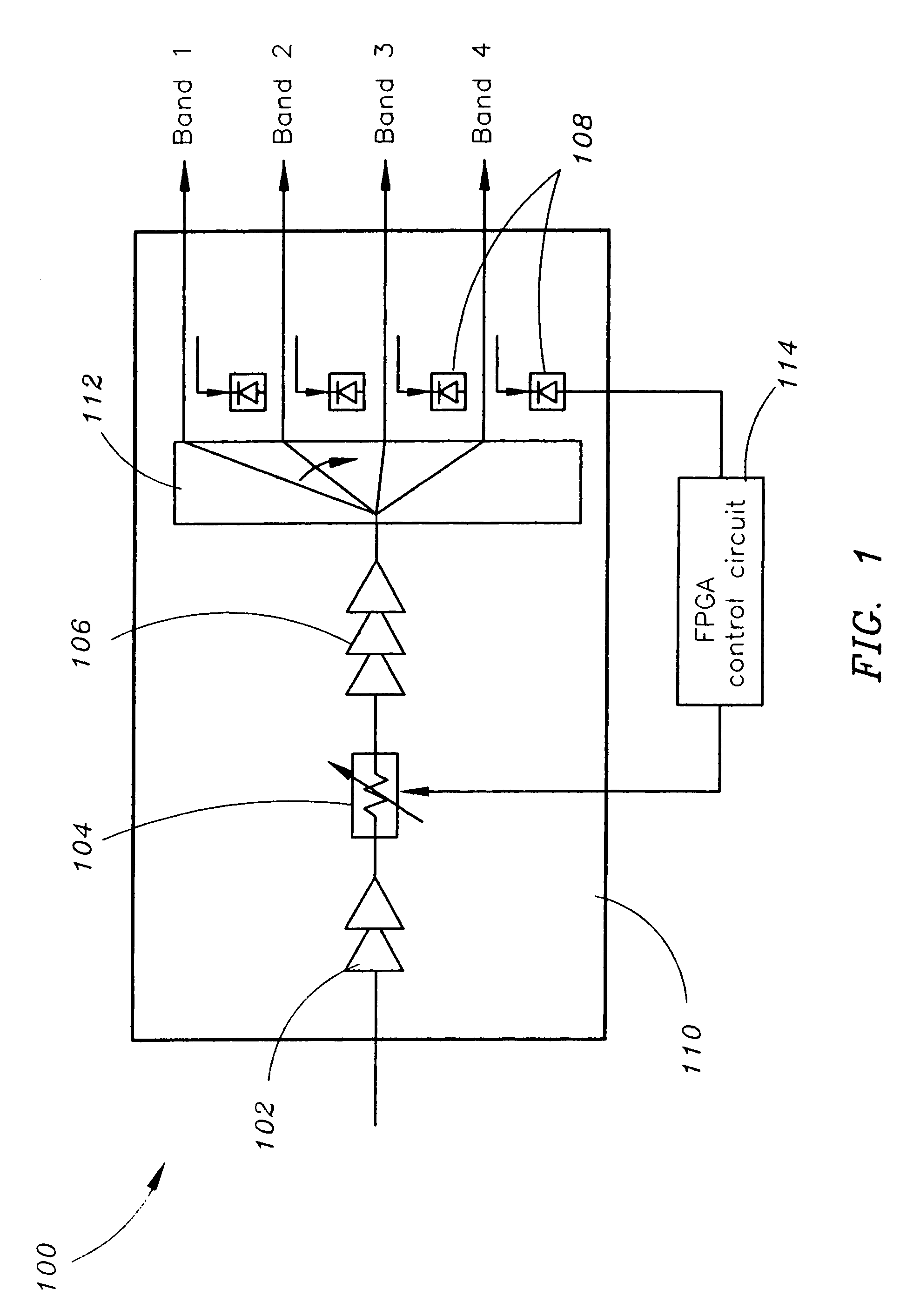
[0019]Referring now to FIG. 1, a block diagram of a power amplifier 100 according to an exemplary embodiment of the present invention is shown. Power amplifier 100 comprises a distributed pre-driver 102 further comprising a digital variable attenuator 104 and a distributed high power amplifier 106. Power amplifier also comprises and an integrated coupler and detector unit 108. Power amplifier 100 may be suitable for implementation in a monolithic microwave integrated circuit (MMIC) device. Specifically, the semiconductor channel for the power amplifier 100 is formed at an interface 110 of the gallium nitride (GaN) layer and the aluminum gallium nitride (AlGaN) layer. Power amplifier may further comprise a GaN based 1×N switch 112 configured to provide channel selection and a gain control circuit 114. In one embodiment, the pow...


PUM


Abstract

A power amplifier comprises a distributed pre-driver, digital signal adjuster, a distributed high power amplifier; and an integrated coupler-detector unit. The distributed pre-driver, the digital signal adjuster, the distributed high power amplifier and the integrated coupler-detector unit are formed at an interface of a Gallium Nitride layer and an Aluminum Gallium Nitride layer of a monolithic microwave integrated circuit device.

Description

FIELD OF THE INVENTION[0001]The present invention relates generally to power amplifiers. More specifically, the present invention relates to a distributed power amplifier in a monolithic microwave integrated circuit.BACKGROUND OF THE INVENTION[0002]In microwave systems such as communication systems and phased array antenna systems, microwave circuitry is often implemented in the form of what is commonly known as a microwave monolithic integrated circuit (MMIC). MMICs are a type of integrated circuit (IC) device that operates at microwave frequencies (1 GHz to 300 GHz). An MMIC device typically performs functions such as microwave mixing, power amplification, low noise amplification and high frequency switching. Inputs and outputs on MMIC devices are frequently matched to the standard 50 ohms.[0003]As stated, one function performed by an MMIC device is power amplification. Typically, an MMIC device employs a group of FET based distributed amplifiers to provide broadband amplification...

Claims


Application Information

Patent Timeline
Patent Type & Authority Patents(United States)
IPC IPC(8): H03F3/60
CPCH03F3/195H03F3/607H03F1/3247H03F2200/204H03F2200/207H03F2200/451
Inventor YU, MARK K.XIE, CHENGGANG
Owner ROCKWELL COLLINS INC
Why Eureka
Try Eureka