Rangefinder with reduced noise receiver

a rangefinder and receiver technology, applied in the field of rangefinders, can solve the problems of reducing the strength affecting the detection affecting the accuracy of the reflected beam,

Inactive Publication Date: 2009-03-24
MEADE INSTRUMENTS
View PDF76 Cites 36 Cited by
  • Summary
  • Abstract
  • Description
  • Claims
  • Application Information

AI Technical Summary

Benefits of technology

[0011]Thus, it would be advantageous to develop a technique and system for increasing a rangefinder receiver's sensitivity by reducing receiver noise. It would also be advantageous to avoid false detection of reflected energy beams from a target by changing the sensitivity of the receiver as a function of time. Further, it would be advantageous to develop a technique and system for calibrating range measurements using data collected each time a rangefinder acquires a range measurement or a set of range measurements. It would also be advantageous to develop a technique and system to correct range measurement errors related to dynamic factors, such as errors that vary with time or environmental conditions.
[0012]Embodiments of the present invention provide a rangefinder and method for measuring distances by measuring the flight time of an energy pulse traveling between the rangefinder and a target. The rangefinder includes a low noise receiver that receives the energy pulse and converts it into a voltage pulse that is compared to a threshold voltage level. In an embodiment, the voltage pulse is filtered, amplified, and clamped to remove noise and improve the signal-to-noise ratio. In an embodiment, the sensitivity of the receiver is increased as a function of time to reduce the likelihood of detecting stray reflections from objects other than the intended target. Moreover, in various embodiments, false detections are reduced by ignoring reflections until a predetermined amount of time has passed, incrementally changing the threshold voltage level, using a time-varying waveform to automatically lower the threshold voltage as a function of time, combinations of the foregoing, or the like.
[0016]In an embodiment, a rangefinder receiver includes means for generating a voltage signal proportional to a beam reflected from a target, means for removing noise from the voltage signal, and means for comparing the voltage signal to a first voltage level.

Problems solved by technology

It can be difficult for conventional receivers to detect a reflected beam because the strength of the reflected beam becomes weaker as a function of distance to the target.
Further, factors such as rain, snow, shrubbery, targets with poor reflectivity, or the like can reduce the strength of the reflected beam.
Background light is typically the largest source of noise during daylight operation of laser rangefinders.
Such noise reduces the signal-to-noise ratio and makes it difficult to detect weak reflections.
While detection depends at least in part on the receiver's sensitivity, a receiver that is too sensitive can generate a false detection of the reflected beam.
False detection may be caused, for example, by reflections from objects that are not the intended target such as shrubs, trees, snow, rain, or other objects in the path between the intended target and the rangefinder.
Weak reflections from such objects can cause an overly sensitive receiver to incorrectly determine that a beam reflected from the intended target has been received.
However, as discussed above, if the sensitivity is too low, valid reflections from distant targets or targets with poor reflectivity cannot be detected.
The accuracy of range measurements is affected by the rangefinder's ability to accurately measure a beam's flight time because small variations can create significant errors in the distance calculated.
Even using such discharging mechanisms, delays in the rangefinder's internal circuitry add additional error to flight time interval measurements.
Some errors caused by the internal circuitry are due to inherent delays that can be initially measured and corrected during, for example, factory calibration and test.
However, some delays caused by the internal circuitry are variable and may change over time.
Further, some delays may change with variations in environmental conditions such as temperature, humidity and the like.

Method used


Image

  • Rangefinder with reduced noise receiver
  • Rangefinder with reduced noise receiver
  • Rangefinder with reduced noise receiver

Examples


Embodiment Construction

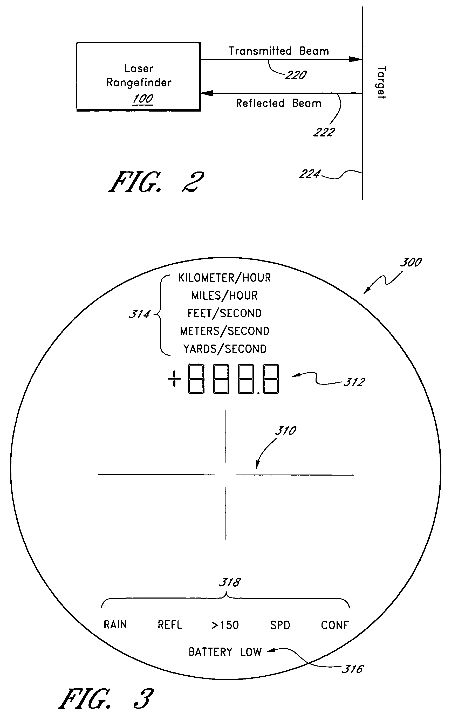
[0033]Aspects or embodiments of the present invention provide a method and rangefinder for measuring a distance between the rangefinder and a target. A rangefinder according to the invention emits an energy pulse towards a target and detects a reflection of the energy pulse from the target. The rangefinder measures an elapsed time between emitting the energy pulse and detecting the energy pulse and, based on the speed of the emitted and reflected energy pulse, converts the elapsed time into a distance measurement.

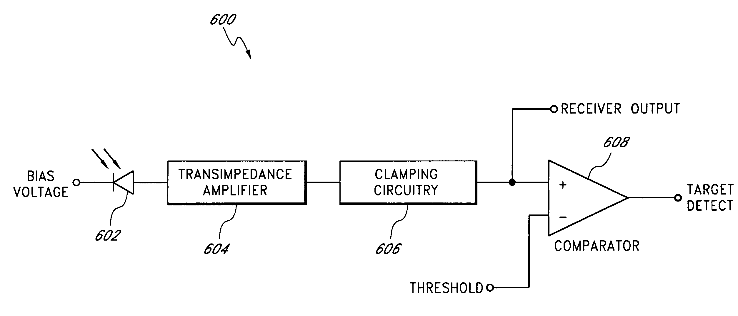
[0034]According to one aspect of the rangefinder system, a receiver with reduced noise is used to detect weak reflections from distant targets or targets with poor reflectivity. In an embodiment, a rangefinder receiver filters, amplifies and clamps a receiver signal comprising receiver noise and a pulse proportional to a light pulse reflected from a target. The receiver removes low frequency noise components generated by a photodiode configured to receive the reflected beam...


PUM


Abstract

A rangefinder and method are provided for measuring a distance between the rangefinder and a target by measuring the flight time of a beam reflected from the target. In an embodiment, a receiver having reduced noise detects weak reflections from the targets or targets with poor reflectivity. The receiver generates a voltage signal proportional to a reflected beam, clamps the voltage signal to remove a portion of the noise therefrom, and compares the voltage signal to a threshold. In some embodiments, the receiver also filters the voltage signal to remove a portion of the noise therefrom. In an embodiment, the sensitivity of the receiver is increased as a function of time to reduce the likelihood of detecting stray reflections from objects other than the intended target. In some embodiments, the rangefinder collects calibration data with each range measurement or group of range measurements. The calibration data comprise a plurality of simulated range measurements.

Description

RELATED APPLICATIONS[0001]This application claims a priority benefit under 35 U.S.C. §119(e) from U.S. Provisional Patent Application No. 60 / 525,621, filed on Nov. 26, 2003. The foregoing application is hereby incorporated by reference herein.BACKGROUND OF THE INVENTION[0002]1. Field of the Invention[0003]The present invention relates to a rangefinder device for measuring a distance to a target.[0004]2. Description of the Related Art[0005]Rangefinders are used to measure distances to targets. Typically, a rangefinder will emit a beam of energy towards a target and detect a reflected beam from the target. In general, the rangefinder measures the time interval between the emission of the transmitted beam and the reception of the reflected beam. This time interval is referred to herein as the “flight time.” The distance from the rangefinder to the target is derived from the speed of the beam and the flight time.[0006]It can be difficult for conventional receivers to detect a reflected ...

Claims


Application Information

Patent Timeline
Patent Type & Authority Patents(United States)
IPC IPC(8): G01C3/08G01S7/481G01S7/487G01S7/497G01S17/10
CPCG01C3/08G01S7/4813G01S7/497G01S17/10G01S7/4873
Inventor LABELLE, JOHN
Owner MEADE INSTRUMENTS
Why Eureka
Try Eureka