
Off-axis catadioptric projection optical system for lithography

a technology of catadioptric projection and optical system, applied in the field of lithography, can solve the problems of complex alignment process, large number of existing systems, significant limitations of existing projection systems, etc., and achieve the effect of reducing field curvatur

Inactive Publication Date: 2009-03-31
ASML HLDG NV
View PDF32 Cites 2 Cited by
  • Summary
  • Abstract
  • Description
  • Claims
  • Application Information

AI Technical Summary

Benefits of technology

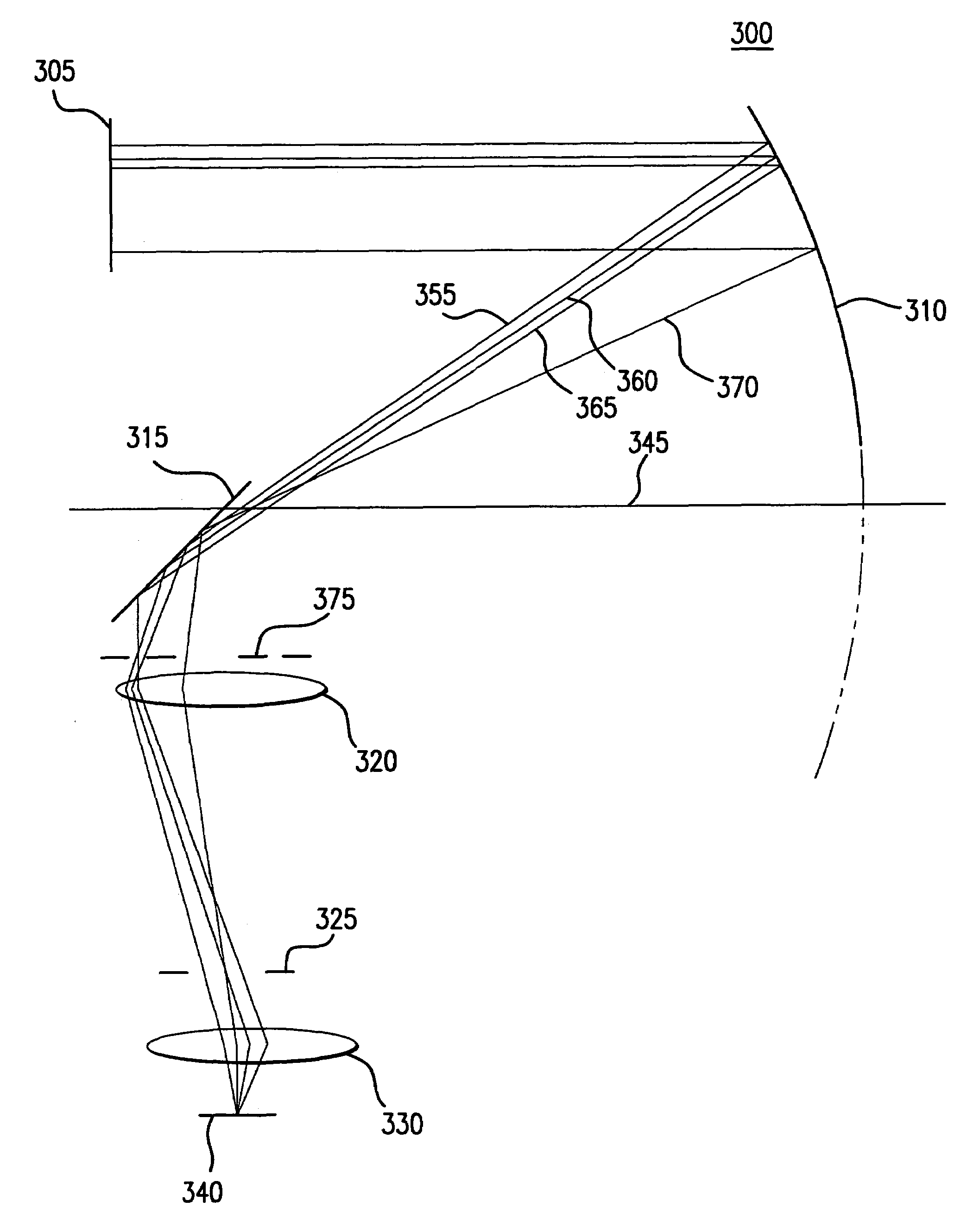
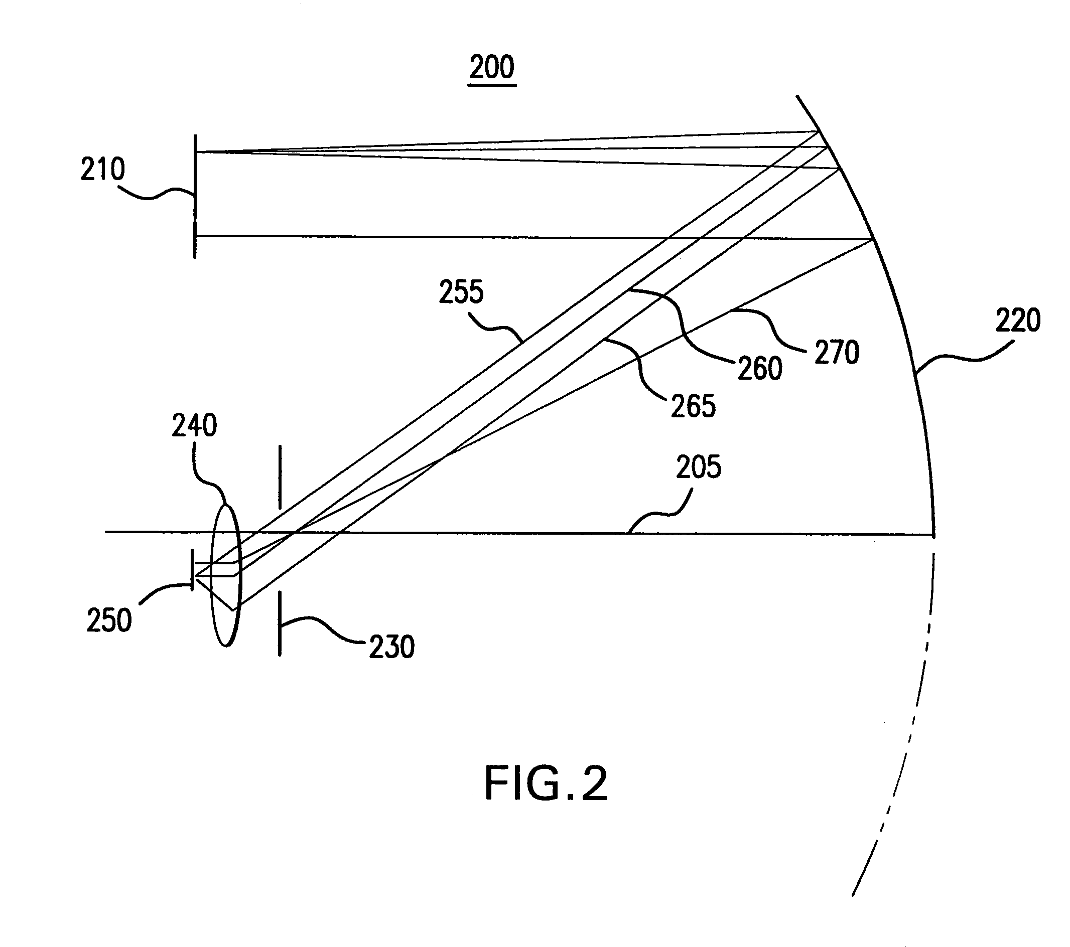
The present invention is about off-axis catadioptric projection systems for use in lithography tools. These systems use both reflective and refractive optical elements to process modulated light to form an image on a substrate. The off-axis mirror segment helps reduce field curvature, which is important for accurate image formation. The different embodiments provide flexibility in design and can further reduce chromatic aberrations. The invention also includes a method to produce a device using a lithographic apparatus with the off-axis mirror segment.

Problems solved by technology

Existing projection systems have significant limitations.
Among these limitations are that existing systems often include a very large number of optical components and are often complicated.
Furthermore, the alignment process is complicated and overall dimensions are large.
Other limitations are found in systems that limit light transmission to only about 25% of the light provided by the pattern generating device.

Method used


Image

  • Off-axis catadioptric projection optical system for lithography
  • Off-axis catadioptric projection optical system for lithography
  • Off-axis catadioptric projection optical system for lithography

Examples


Embodiment Construction

[0019]While the present invention is described herein with reference to illustrative embodiments for particular applications, it should be understood that the invention is not limited thereto. Those skilled in the art with access to the teachings provided herein will recognize additional modifications, applications, and embodiments within the scope thereof and additional fields in which the invention would be of significant utility.

[0020]The term “pattern generator” as here employed should be broadly interpreted as referring to any device that can be used to endow an incoming radiation beam with a patterned cross-section, so that a desired pattern can be created in a target portion of the substrate. The terms “light valve” and “Spatial Light Modulator” (SLM) can also be used in this context. Examples of such patterning devices are discussed below.

[0021]A programmable mirror array may comprise a matrix-addressable surface having a viscoelastic control layer and a reflective surface. ...


PUM


Abstract

An off-axis catadioptric projection optical systems for use in lithography tools for processing modulated light used to form an image on a substrate is provided. In one embodiment the optical system includes an off-axis mirror segment, a fold mirror, a relay, an aperture stop and a refractive lens group. Modulated light is transmitted through the system to form an image on a substrate. In a second embodiment the projection system includes an off-axis mirror segment, an aperture stop and a refractive lens group. In a third embodiment the projection system includes an off-axis mirror segment, a negative refractive lens group, a concave mirror, a relay, an aperture stop, and a refractive lens group. A method to produce a device using a lithographic apparatus including a projection system with an off-axis mirror segment as the first element in a projection optics system is also provided.

Description

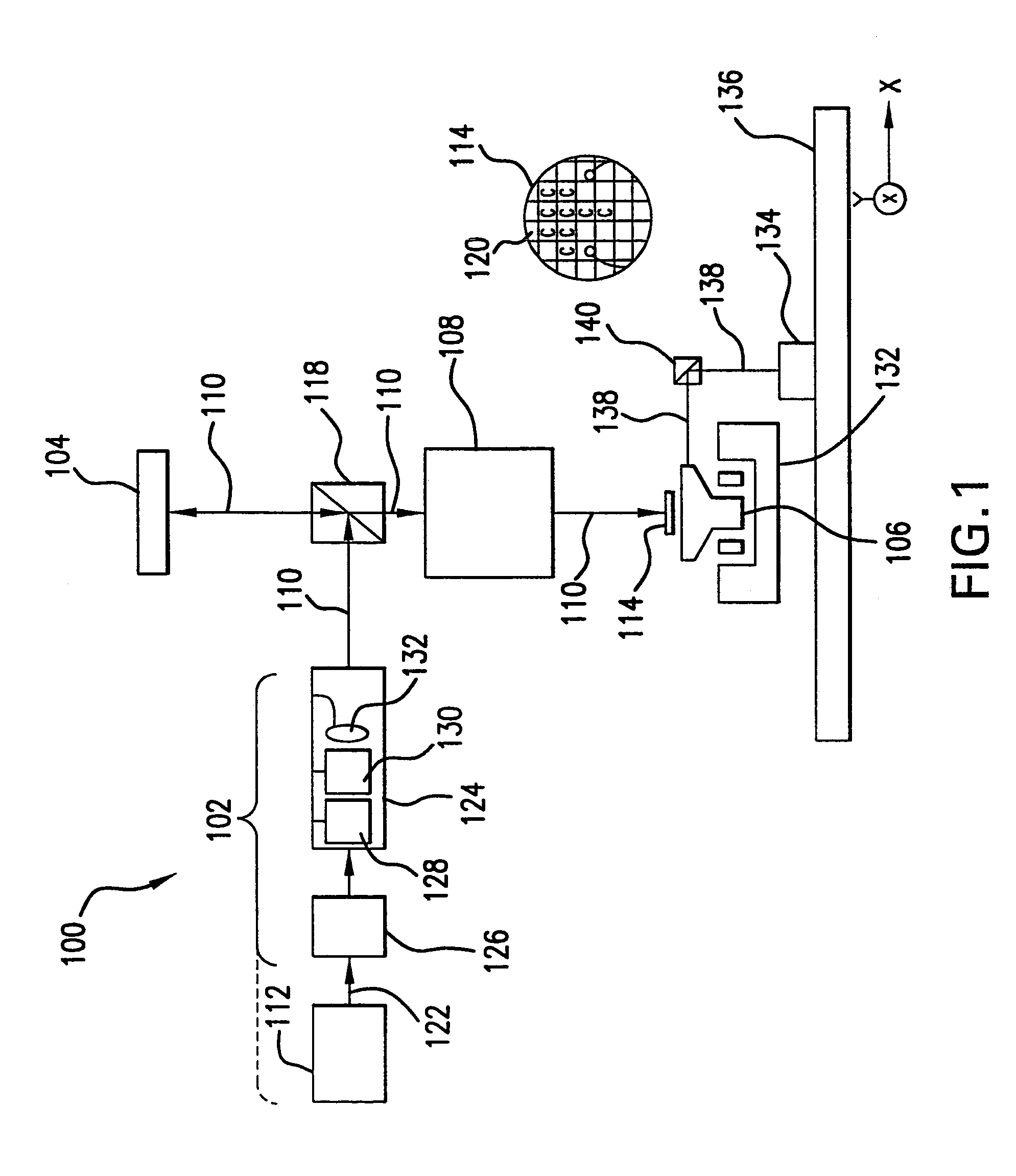
BACKGROUND OF THE INVENTION[0001]1. Field of the Invention[0002]The present invention relates to lithography, and more particularly, to projection optics used in lithography.[0003]2. Background of Invention[0004]Lithography systems are used to print features in a variety of manufacturing applications. Photolithography systems use a mask or reticle to expose features onto an object. In semiconductor manufacturing, for example, a reticle is exposed by an exposure beam. An optical system then projects a reduced image of the reticle onto a silicon wafer. In this way, circuit features can be printed on a semiconductor substrate.[0005]Maskless lithography systems have been developed that do not require use of a mask or reticle. Current maskless lithography systems project a pattern to be printed onto a moving object. For example, a pattern of circuit features can be projected onto a moving wafer or flat panel display. In one example, a silicon wafer can be coated with a photoresist. The p...

Claims


Application Information

Patent Timeline
Patent Type & Authority Patents(United States)
IPC IPC(8): G03B27/42G03B27/70
CPCG03B27/54G03F7/70225G02B17/0812
Inventor SMIRNOV, STANISLAVOSKOTSKY, MARK
Owner ASML HLDG NV
Learn More