Imaging lens

An imaging lens and lens technology, applied in the field of imaging lenses, can solve the problems of small optical magnification, large distortion, and small range of working object distance, etc., to reduce tolerance sensitivity, reduce field curvature and astigmatism, improve The effect of image quality

Pending Publication Date: 2021-02-05
舜宇光学(中山)有限公司
View PDF0 Cites 2 Cited by
  • Summary
  • Abstract
  • Description
  • Claims
  • Application Information

AI Technical Summary

Problems solved by technology

However, the current machine vision lenses on the market have a small optical magnification, a small imaging frame, large distortion, uneven picture definition, and a small range of working object distance. Although such machine vision lenses have a wide shooting range , but its imaging is not delicate enough, the dynamic range is not high when imaging, and the color and contrast are not good enough
[0004] As machine vision is used more and more widely, the requirements for machine vision imaging systems are getting higher and higher. The current machine vision lenses on the market are increasingly unable to meet the needs of the market, especially in some high-end cameras that require high imaging quality. Precision high-tech fields are severely limited

Method used


Image

  • Imaging lens
  • Imaging lens
  • Imaging lens

Examples


Embodiment approach 1

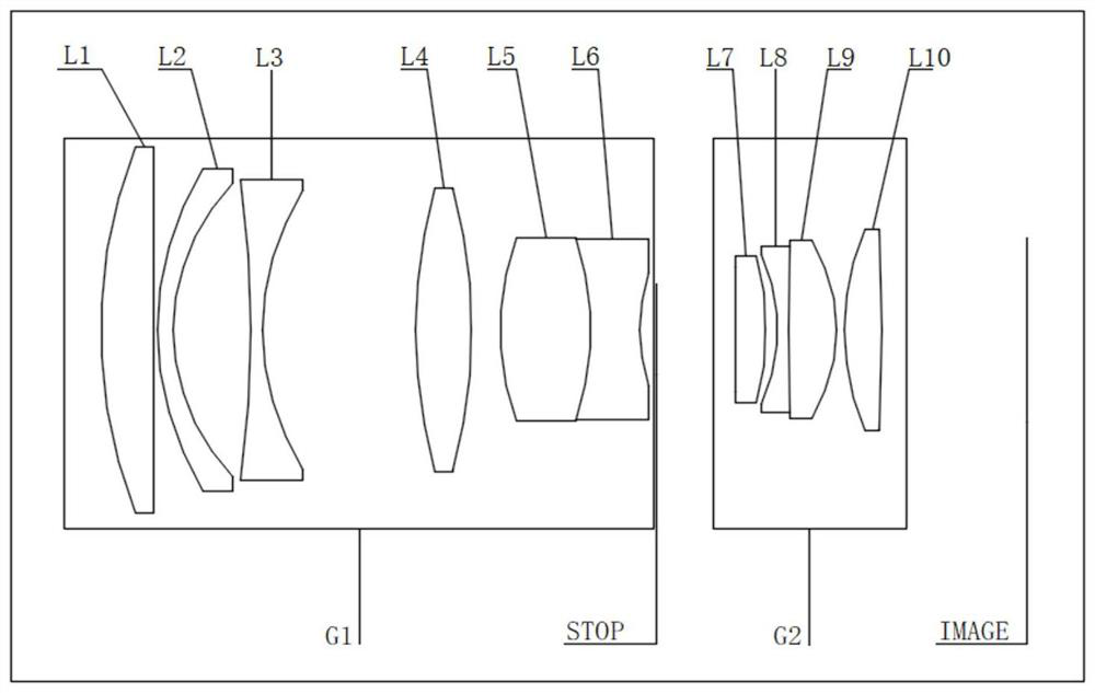
[0067] figure 1 is a schematic diagram showing the structure of the imaging lens according to Embodiment 1 of the present invention.

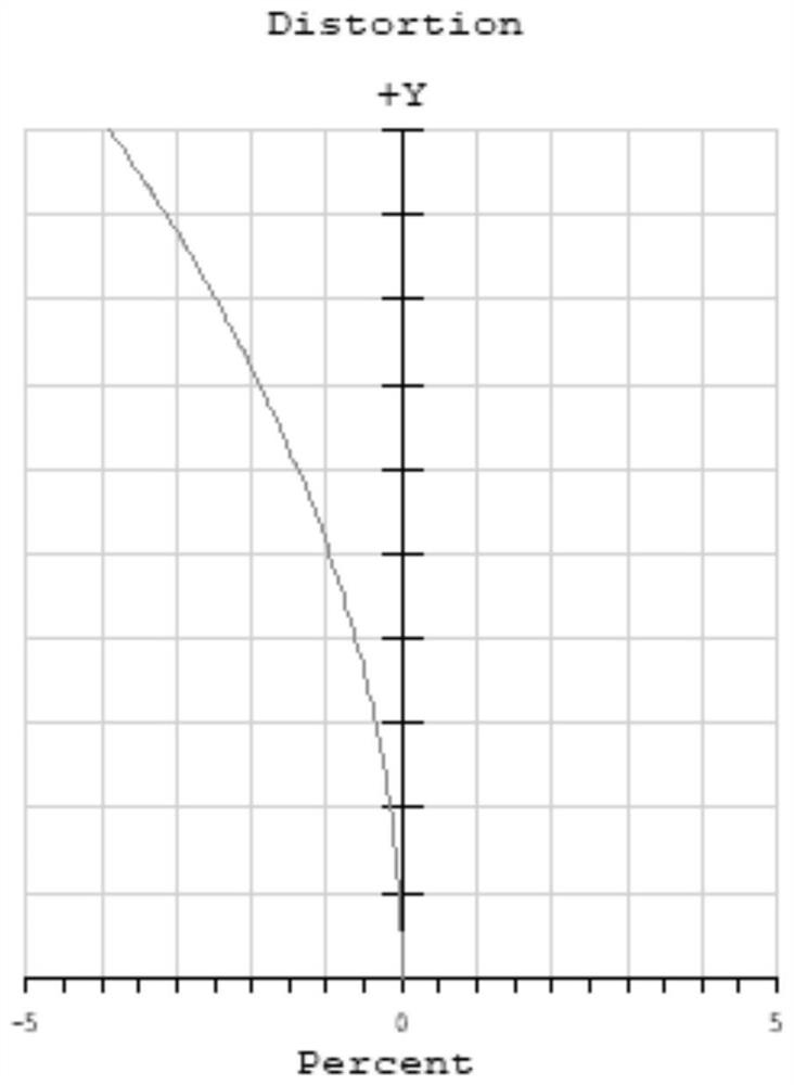
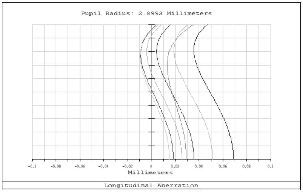
[0068] The total length of the optical system in Embodiment 1 is TTL=48.581mm, the focal length of the system is f=13.5mm, and the F-number FNO=1.4.

[0069] The following table 2 lists the relevant parameters of each lens of the present embodiment, including surface type, radius of curvature, thickness, refractive index of material, Abbe number:

[0070]

[0071]

[0072] Table 2

[0073] combine figure 1 As shown, in this embodiment, the first lens group G1 includes 6 lenses (L1-L6), wherein the lens L5 and the lens L6 form a doublet lens. The second lens group G2 includes 4 lenses (L7-L10), wherein the lens L8 and the lens L9 are doublet lenses. The refractive index ND and Abbe number VD of the fourth lens in the first lens group G1 are 1.90 and 23.5, respectively. The refractive index ND2 and Abbe number VD2 of the third lens in ...

Embodiment approach 2

[0076] Image 6 is a schematic diagram showing the structure of the imaging lens according to Embodiment 2 of the present invention.

[0077] The total length of the optical system in Embodiment 2 is TTL=45.08mm, the focal length of the system is f=14mm, and the F-number FNO=2.0.

[0078] The following table 3 lists the relevant parameters of each lens of this embodiment, including surface type, radius of curvature, thickness, refractive index of material, Abbe number:

[0079]

[0080]

[0081] table 3

[0082] combine Image 6 As shown, in this embodiment, the first lens group G1 includes five lenses (L1-L5), wherein the lenses L4 and L5 are doublet lenses. The second lens group G2 includes 4 lenses (L6-L9), wherein the lens L7 and the lens L8 are doublet lenses. The refractive index ND and Abbe number VD of the third lens in the first lens group G1 are 1.98 and 16.5, respectively. The refractive index ND2 and Abbe number VD2 of the third lens in the second lens g...

Embodiment approach 3

[0085] Figure 11 is a schematic diagram showing the structure of the imaging lens according to Embodiment 3 of the present invention.

[0086] The total length of the optical system in Embodiment 3 is TTL=53.565 mm, the focal length of the system is f=18.49 mm, and the F-number FNO=1.8.

[0087] The following table 4 lists the relevant parameters of each lens of this embodiment, including surface type, radius of curvature, thickness, refractive index of material, Abbe number:

[0088]

[0089]

[0090] Table 4

[0091] combine Figure 11 As shown, in this embodiment, the first lens group G1 includes 6 lenses (L1-L6), wherein the lens L5 and the lens L6 form a doublet lens. The second lens group G2 includes 4 lenses (L7-L10), wherein the lens L8 and the lens L9 are doublet lenses. The refractive index ND and Abbe number VD of the fourth lens in the first lens group G1 are 1.85 and 24.2, respectively. The refractive index ND2 and Abbe number VD2 of the third lens in ...


PUM


Abstract

The invention relates to an imaging lens which comprises a first lens group (G1) with positive focal power, a diaphragm (STOP) and a second lens group (G2) with positive focal power which are sequentially arranged from an object side to an image side, the first lens group (G1) is a fixed group, and the second lens group (G2) is a focusing lens group capable of moving along an optical axis; the first lens group (G1) comprises at least three positive focal power lenses and two negative focal power lenses. The imaging lens provided by the invention can realize the characteristics of large aperture, high resolution, low distortion, uniform image quality, wide working object distance range, good color rendition degree and high contrast ratio.

Description

technical field [0001] The invention relates to the field of optical devices, in particular to an imaging lens. Background technique [0002] Machine vision refers to the use of machines instead of human eyes for measurement and judgment, converting the captured target into an image signal, and sending it to a dedicated image processing system to obtain the shape information of the captured target. According to the pixel distribution and brightness, color and other information, Transformed into digital signals; the image system performs various operations on these signals to extract the characteristics of the target, such as position, size, appearance, etc., and then outputs the results according to preset conditions to realize functions such as automatic identification, judgment, and measurement. [0003] Therefore, the imaging system used for machine vision has very high requirements on pixels, picture uniformity, distortion, brightness, and color reproduction. However, t...

Claims


Application Information

Patent Timeline
Patent Type & Authority Applications(China)
IPC IPC(8): G02B15/167
CPCG02B15/167
Inventor 胡可欣李增辉
Owner 舜宇光学(中山)有限公司
Why Eureka
Try Eureka