
Hierarchical data compression system and method for coding video data

a data compression and data compression technology, applied in the field of data compression, can solve the problems of adversely affecting the quality of the video being viewed, high frequency being added to the encoded video data, and traditional video coding techniques that do not lend themselves to hierarchical video coding, so as to reduce the spatial aliasing

Inactive Publication Date: 2009-03-31
MICROSOFT TECH LICENSING LLC
View PDF6 Cites 25 Cited by
  • Summary
  • Abstract
  • Description
  • Claims
  • Application Information

AI Technical Summary

Benefits of technology

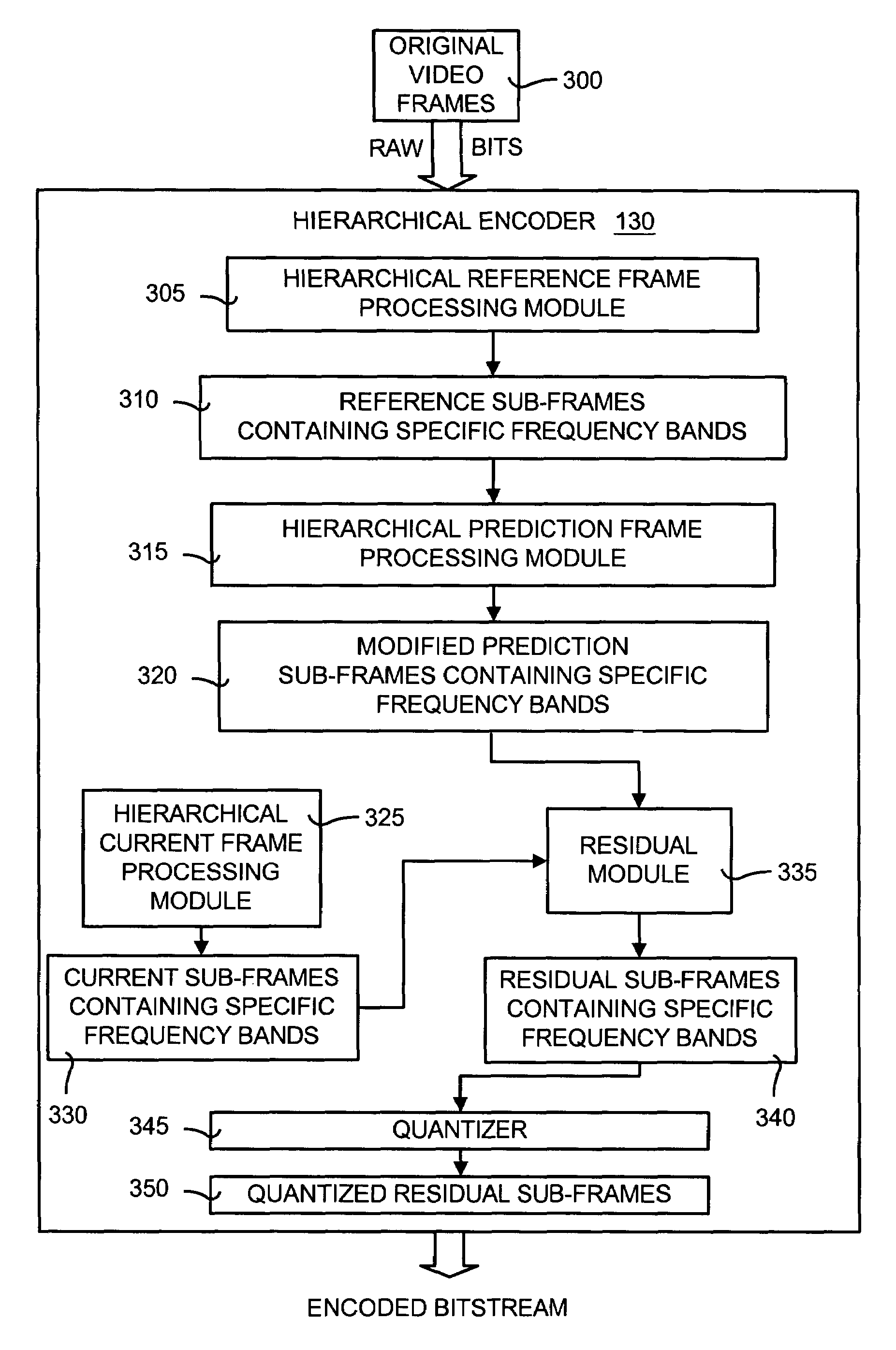
[0010]The hierarchical data compression method divides a video frame into a plurality of layers that represents a particular level of resolution. Moreover, each layer contains a unique frequency band containing a range of frequencies. Each of the layers, when taken together, provides the full resolution of the video frame. Each of the layers can be encoded and decoded independently of each other. Moreover, a layer can be encoded and decoded using elements (such as reference, predicted and current frames) at the same layer as the layer being processed or at a lower layer. Thus, a current layer can be processed using a layer of equal or lower resolution and frequency band. When motion compensation is used for coding, each predicted sub-frame can be obtained from reference frame and current frames at the same or lower layer. After prediction, each of the predicted sub-frames is filtered to remove any frequencies outside the frequency band for that layer. This restricts the frequency band in the predicted sub-frame to the original frequency band in the reference sub-frame for that layer. Ideally, frequency bands are oversampled to reduce spatial aliasing effects.

Problems solved by technology

However, traditional video coding techniques do not lend themselves to hierarchical video coding.
In addition, block boundaries often will present sharp discontinuities that result in high frequencies being added to that encoded video data that were not present in the original source and do not belong.
This results in visible block artifacts that adversely affect the quality of the video being viewed.
Although hierarchical video coding technique do exists, they tend to follow the same approach used in image coding, with little success.
This technique can prove to be a problem if data is not received during transmission from the encoder to the decoder.

Method used


Image

  • Hierarchical data compression system and method for coding video data
  • Hierarchical data compression system and method for coding video data
  • Hierarchical data compression system and method for coding video data

Examples


working example

VI. Operational Details and Working Example

[0062]FIG. 8 is a block / flow diagram illustrating an exemplary implementation of the operation of the hierarchical reference frame processing module 305 shown in FIG. 3. In this exemplary implementation, block-based motion compensation is used. Referring to FIG. 8, a reference frame is obtained for use in the hierarchical reference frame processing module 305. In traditional block-based motion compensation, the reference frame 800 is used to produce motion compensation vectors. Instead, the hierarchical reference frame processing module 305 divides the reference frame 800 into several frequency-specific bands. For example, in the exemplary implementation shown in FIG. 8, the reference frame 800 is divided into a low frequency sub-frame 810, a mid frequency sub-frame 820, and a high frequency sub-frame 830. It should be noted that in other implementations the reference frame 800 may be divided into a greater or lesser number of sub-frames.

[0...


PUM


Abstract

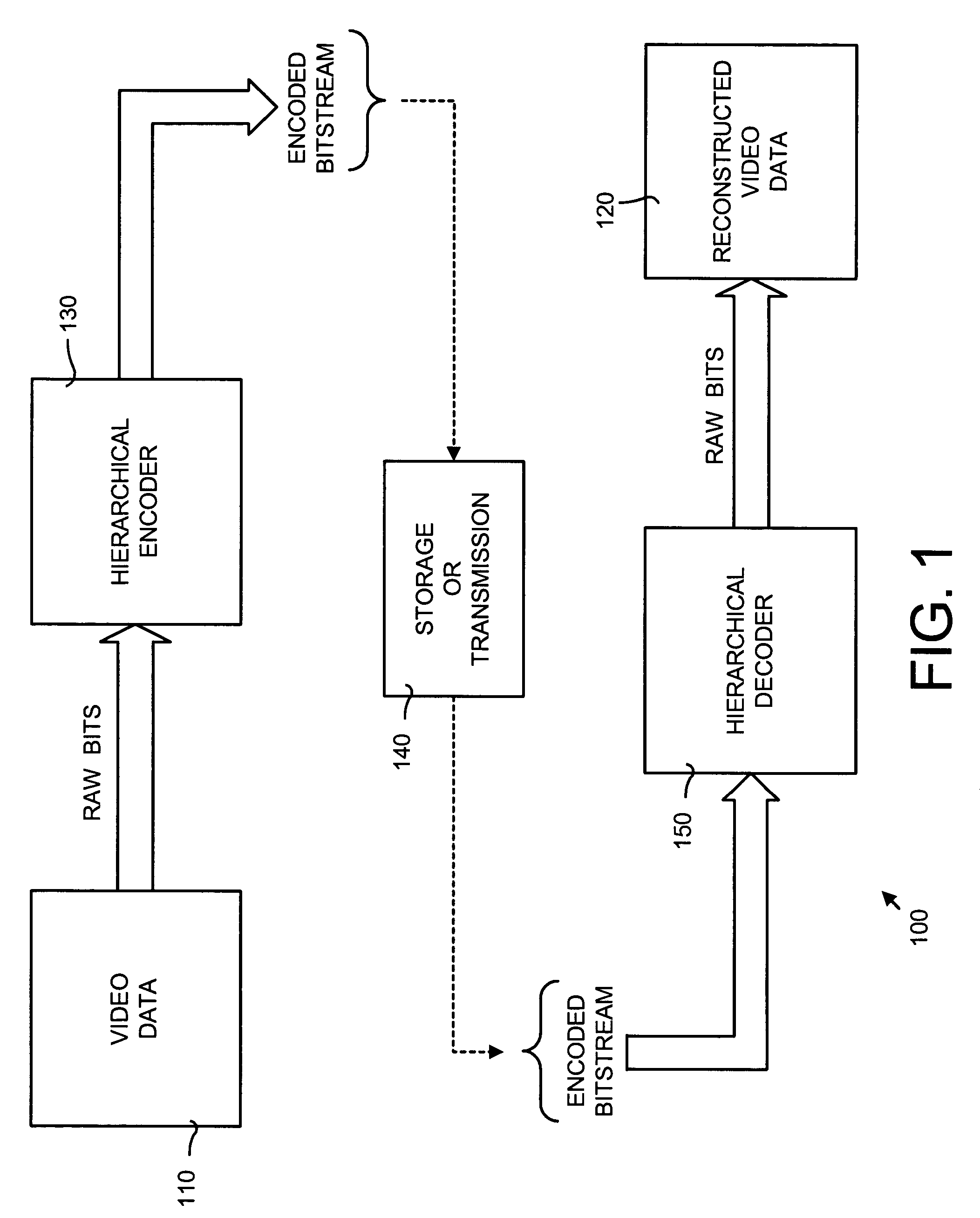
A hierarchical data compression system and method for encoding and decoding video data by dividing each video frame of the video data into independent layers. Each of the layers contains a specific frequency band that is less than the entire frequency spectrum contained in the video frame. This impendency allows each layer to be encoded and decoded independently of other layers. Because each layer contains a specific frequency band, any unwanted and extraneous frequencies that arise during encoding that are not present in the original source are automatically removed. In general, the hierarchical data compression method divides video frames into layers, with each layer containing a specific frequency band. The layers then are encoded. Later, the layers are decoded to recover the video frames. The hierarchal data compression system includes a hierarchical encoder and decoder for facilitating independent encoding and decoding of each layer of the divided video frames.

Description

TECHNICAL FIELD[0001]The present invention relates in general to data compression and more particularly to a hierarchical data compression system and method for encoding and decoding video data by dividing the video data into layers whereby each layer is encoded and decoded independently of other layers.BACKGROUND OF THE INVENTION[0002]Data compression is widely used and vital to the high-speed and efficient exchange and storage of data. One of the goals of data compression is to compress original data as much as possible, transmit or store the compressed data, and then uncompress the compressed data to reconstruct the original data. Better compression means that, at a given signal to noise ratio, the compressed data are smaller and thus use fewer bits of information to represent the original data. Using fewer bits of information both reduces the time required to transmit the compressed data and the amount of storage space needed to store the compressed data. This can significantly ...

Claims


Application Information

Patent Timeline
IPC IPC(8): H04N7/12H04B1/66H04N11/02H04N11/04H04N7/26
CPCH04N19/63H04N19/61
Inventor FLORENCIO, DINEI A. F.
Owner MICROSOFT TECH LICENSING LLC
Learn More