Wood collection and reducing machine

a technology for reducing machines and wood, which is applied in the field of drum chippers and shredders, can solve the problems of low compliance with collection rules, smoke and pollutants discharged into the air, and affecting the cutting efficiency of wood, and achieves the effect of improving cutting efficiency

Inactive Publication Date: 2009-04-07
BARKO SPECIALTY EQUIP
View PDF18 Cites 12 Cited by
  • Summary
  • Abstract
  • Description
  • Claims
  • Application Information

AI Technical Summary

Benefits of technology

[0010]The present invention addresses one or more of the above mentioned problems and others by providing a shredder for reducing materials that includes a tapered cutting drum having an imperforate outer surface whereby to carry reduced material externally and radially outwardly of the cutting drum. A tapered cutting drum provides a cutting surface with a plurality of cutting speeds and torque to improve cutting efficiency.

Problems solved by technology

Urban removal of wood and debris at the curbside is presently accomplished using a number of labor intensive or environmentally unfriendly methods.
Burning, although less used today than years past, results in smoke and pollutants being discharged into the air.
This method is particularly a problem during days of high pressure which forces smoke to hover at low altitudes and create a nuisance.
One problem with bundling is that compliance with proper collection rules is low.
Compliance problems typically arise when people bundle branches in excess of the size or weight designated by collection crews.
Problems can also arise when people fail to properly tie the bundles.
Bundles that fail to comply with collection rules are typically left at the curbside by collection crews and may sit for weeks thereby becoming an eye sore and a road hazard.
Although this method is fairly effective at reducing wood debris, the method fails in many other respects.
First, the method provides an inefficient use of labor, as it requires multiple crewmembers to drive the truck and handle the branches.
Secondly, present day chippers and shredders generate large amounts of noise pollution.
Excessive noise pollution arises from both the high speed cutting implements and from the high power blower systems.
Noise pollution also arises from high speed impacting of the cutting implements upon the material being shredded.
Present day shredders also are very dangerous.
If an operator fails to pay close attention to the job at hand, the operator can be pulled into the shredder and severely injured.
Another hazard arises from flying debris.

Method used


Image

  • Wood collection and reducing machine
  • Wood collection and reducing machine
  • Wood collection and reducing machine

Examples


Embodiment Construction

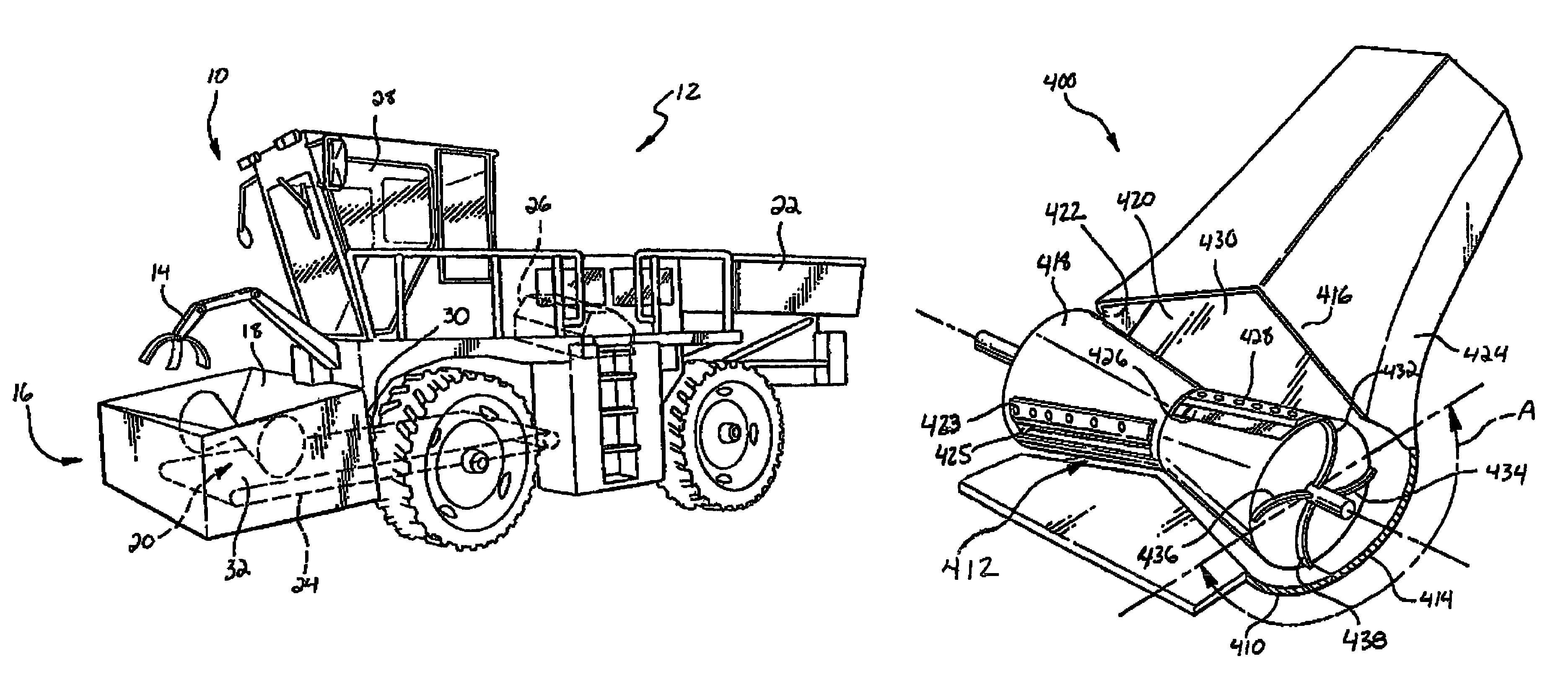
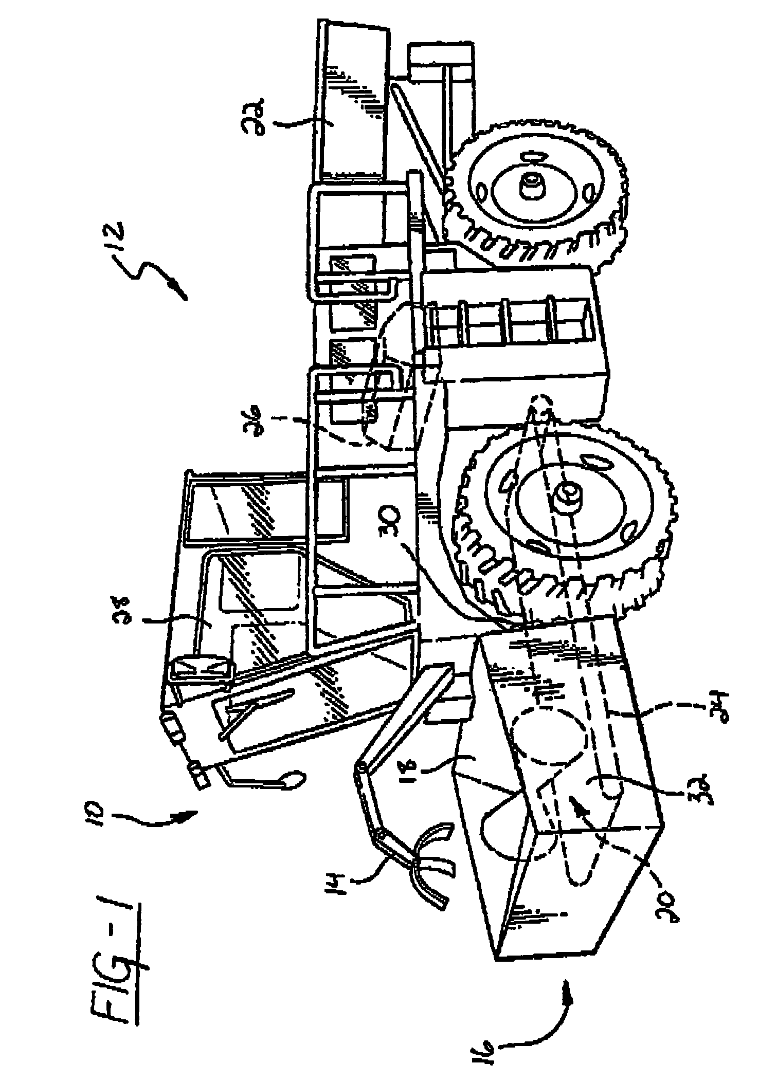
[0032]Now with more particularity and with reference to FIG. 1, generally depicted therein at 10 is a self propelled embodiment of a machine for collecting and shredding wood.

[0033]The machine includes a prime carrier 12; a debris collector 14 operatively attached to the prime carrier 12; and a shredder assembly 16. The shredder assembly 16 has a wood input 18 and an output 20. A storage bin 22 for holding reduced or shredded wood is attached to the prime carrier 12. A conveyor 24 is disposed between the output 20 and the storage bin 22. The conveyor 24 is for moving reduced wood away from the output 20 of the shredder assembly 16 to the storage bin 22.

[0034]The prime carrier 12 is a motorized vehicle having an engine 26 and an operator compartment or cab 28. Preferably the prime carrier has wheels, as opposed to tracks, to allow for street travel at posted speeds and for fuel economy. The prime carrier 12 provides support, mobility and may provide power to heavy accessories, includ...


PUM


Abstract

A shredder for reducing material which includes a conical cutting drum rotatably positioned within a housing and having an imperforate outer surface so as to carry shredded material radially with and externally of the drum; at least one cutting implement disposed about the outer surface of the cutting drum; an anvil disposed adjacent to the cutting drum; a bellyband wrapping around and conforming to the drum; and a transition interconnecting the bellyband with a discharge port and having a cross sectional configuration that inversely mirrors the cross sectional configuration of the bellyband.

Description

CROSS-REFERENCE TO RELATED APPLICATIONS[0001]The present invention relates to, and is entitled to the benefit of the earlier filing date and priority of: U.S. Provisional Patent Application No. 60 / 269,653, filed Feb. 16, 2001, entitled “Wood Collection and Reducing Machine”, U.S. Provisional Patent Application No. 60 / 286,477, filed Apr. 25, 2001, entitled “Wood Collection and Reducing Machine”, and to U.S. Non-provisional patent application Ser. No. 10 / 076,638 filed Feb. 16, 2002 now U.S. Pat. No. 6,824,089, entitled “Wood Collection and Reducing Machine” to the same inventors hereof, the disclosures of which are hereby incorporated herein by reference.BACKGROUND OF THE INVENTION[0002]I. Field of the Invention[0003]The present invention pertains to machines for collecting, reducing, compacting and removing wooden materials, and more particularly to drum chippers and shredders.[0004]II. Description of the Background[0005]Urban removal of wood and debris at the curbside is presently a...

Claims


Application Information

Patent Timeline
Patent Type & Authority Patents(United States)
IPC IPC(8): B02C13/20A01G3/00B02C18/14B02C18/18B27L11/00
CPCA01G3/002A01G23/067B02C18/144B02C18/145B02C18/186B02C21/026B27L11/002B02C2201/066
Inventor GROSS, THOMAS R.SMITH, EARL R.
Owner BARKO SPECIALTY EQUIP
Why Eureka
Try Eureka