
Structure of planar illuminator

a technology of illuminator and microstructure, which is applied in the direction of instruments, lighting and heating apparatus, optical elements, etc., can solve the problems of not being able to be tiled up, heavy weight, complex and costly, etc., and achieves the effect of simple and easy manufacturing, cost effective, and suitable for mass production

Inactive Publication Date: 2009-04-07
NATIONAL TSING HUA UNIVERSITY
View PDF1 Cites 19 Cited by
  • Summary
  • Abstract
  • Description
  • Claims
  • Application Information

AI Technical Summary

Benefits of technology

"The present invention provides a planar illuminator with a light source frame having a hollow reflective cavity. This structure is simple and easy to manufacture, cost-effective, and suitable for mass production. The illuminator has increased uniformity and brightness of the illumination light output by arranging tilted plates and reflective coatings or optical films. The weight of the illuminator is light, making it suitable for use in large-area backlight modules for displays. The technical effects of the invention include achieving required uniformity and brightness, reducing weight, and promoting uniformity and quality of the illumination light output."

Problems solved by technology

However, the solid light guide 14 with the microstructure 142 is complex and costly.
Furthermore, its weight is heavy such that it is not suitable to be tiled up for the large size display applications.

Method used


Image

  • Structure of planar illuminator
  • Structure of planar illuminator
  • Structure of planar illuminator

Examples


Embodiment Construction

[0019]The detailed explanation of the present invention is described as following. The described preferred embodiments are presented for purposes of illustrations and description, and they are not intended to limit the scope of the present invention.

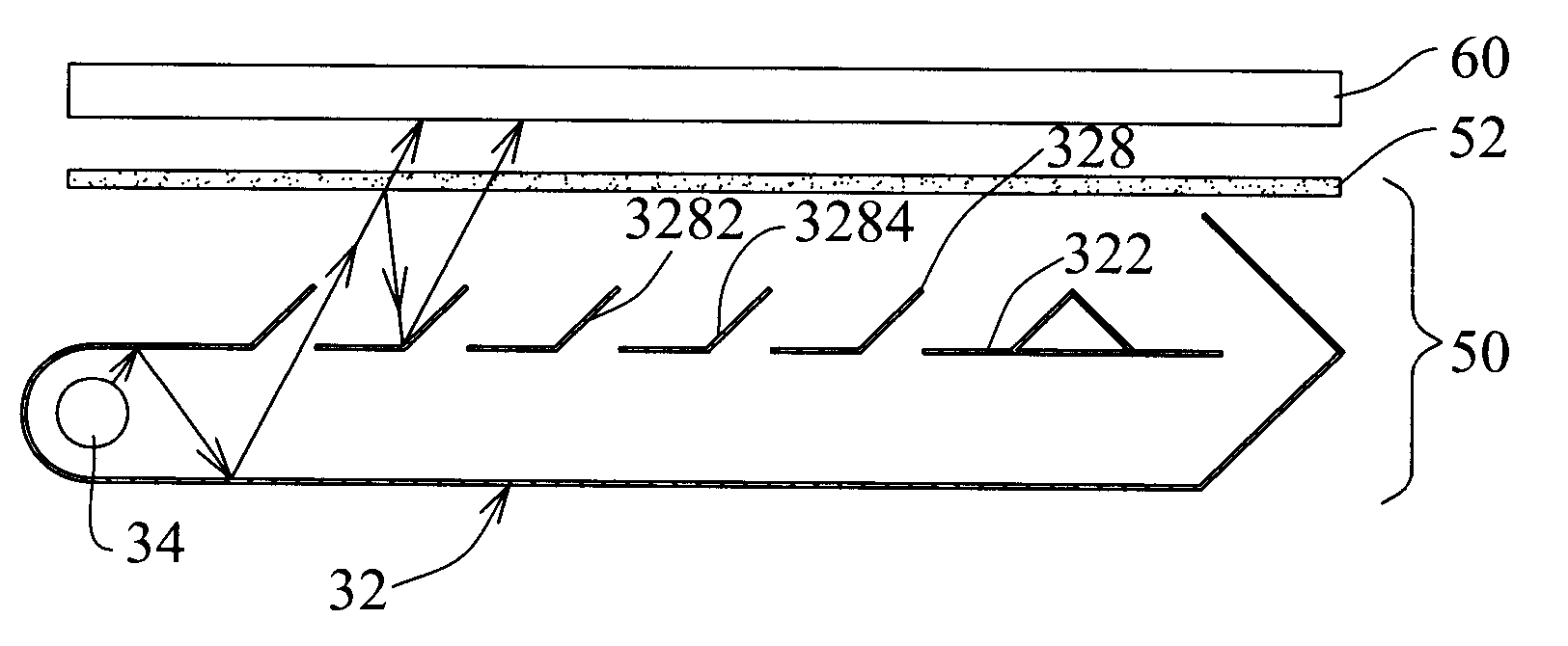
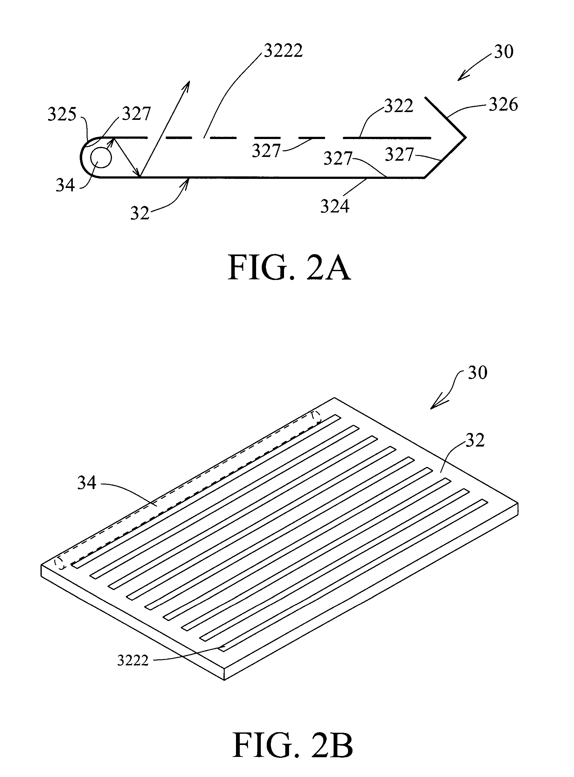
[0020]Firstly, please refer to FIG. 2A and FIG. 2B, which are the side-view and solid schematic diagrams for the structure of the planar illuminator 30 according to one embodiment of the present invention. A planar illuminator 30 includes a light source frame 32 and a light source 34. The light source frame 32 includes: a top plate 322 having a plurality of slits 3222; a bottom plate 324 arranged apart from the top plate 322; and two edge plates 325, 326 arranged oppositely, wherein each of the edge plates 325, 326 has a top end and a bottom end, and both of the bottom ends are separately connected with the bottom plate 324, wherein the inner surfaces of the top plate, the bottom plate and the edge plates form a reflective cavity. The li...


PUM


Abstract

A structure of a backlight module, which includes: a light source frame, including: a top plate having a plurality of slits; a bottom plate arranged apart from the top plate; and at least two edge plates arranged oppositely, wherein each of the edge plates has a top end and a bottom end, and both of the bottom ends are separately connected with the bottom plate; wherein the inner surfaces of the top plate, the bottom plate and the edge plates form a reflective cavity; and at least one light source arranged in the reflective cavity. There are several advantages of the backlight module according to the present invention, which includes: 1. the required uniformity and brightness of the backlight module are achieved; 2. its weight is largely reduced; and 3. it can be tiled up to form a large-area backlight module for a large size display.

Description

BACKGROUND OF THE INVENTION[0001]1. Field of the Invention[0002]The present invention relates to a planar illuminator, and more particularly, to a backlight module with a light source frame having a hollow reflective cavity.[0003]2. Description of the Prior Art[0004]The Liquid Crystal Display (LCD) is the most popular Flat Panel Display (FPD) recently. It has many benefits such as low power consumption, thin shape, light weight, and low driving voltage, etc. Therefore, it is widely applied for many electronic apparatuses, such as the notebook computer, the laptop computer and the television.[0005]Because LCD is not self-illuminated, it needs a backlight module to provide the light source for the image display. Conventionally, the backlight module can be categorized into two types, namely the direct-illumination type and the edge-illumination type. The edge-illumination backlight module is mostly used for the small and medium size LCD, which uses the Cold Cathode Fluorescent Lamp (CC...

Claims


Application Information

Patent Timeline
Patent Type & Authority Patents(United States)
IPC IPC(8): G09F13/04
CPCG02B6/0055G02B6/0096G02F1/133615
Inventor CHEN, CHENG-HUAN
Owner NATIONAL TSING HUA UNIVERSITY
Learn More