Electron tubes

a technology of electron emissivity and electrodes, applied in the field of electron tubes, can solve the problems of difficult bending and welding of metal strips, dust sputtering, and damage to electron emissivity materials (such as carbonates) coated over the surface of filaments, and achieves the effects of simple structure, easy loading of filaments, and low manufacturing cos

Inactive Publication Date: 2009-04-14
FUTABA CORPORATION
View PDF8 Cites 0 Cited by
  • Summary
  • Abstract
  • Description
  • Claims
  • Application Information

AI Technical Summary

Benefits of technology

[0014]Moreover, another object of the present invention is to provide a vibration absorbing means that is easily attachable to linear members such as filaments, without welding vibration absorbers, and allows small-sizing the installation space for a vibration absorber.
[0026]According to the present invention, the getter shielding member used as the position regulation member has the function of a stopper of the vibration absorber. Accordingly, the number of components can be reduced without mounting a dedicated stopper and the installation space for the dedicated stopper is omitted. Moreover, the vibration absorber and the holder of the present invention, which have the function of a getter shielding member, can improve the getter shielding effect. In the fluorescent luminous tube for an optical print head, when the cathode filament vibrates due to external vibration, the current flowing from the cathode filament to the anode electrode changes, so that the luminous amount of a fluorescent substance varies. As a result, the image to be formed is subjected to a large influence such as gradation variation. However, the vibration absorber according to the present invention attenuates the vibration of the cathode filament in a short time and is preferable as a vibration absorber for a fluorescent luminous tube, particularly, for an optical head.

Problems solved by technology

However, since the filament is very thin (for example, about 30 μm), it is difficult to bend and weld the metal strip and cinder dusts are sputtered out from the metal strip during welding.
Moreover, an electron emissive material (such as carbonate), which is coated over the surface of a filament, may be damaged due to high welding temperatures during welding.
This leads to largely cooling the end of a filament by the vibration absorber.
Finally, this becomes an obstacle to miniaturization of electron tubes, such as fluorescent luminous displays.

Method used


Image

  • Electron tubes
  • Electron tubes
  • Electron tubes

Examples


Embodiment Construction

[0037]Embodiments of the present invention will be described below by referring to FIGS. 1 to 8. In the respective drawings, the same numerals are attached to the common elements.

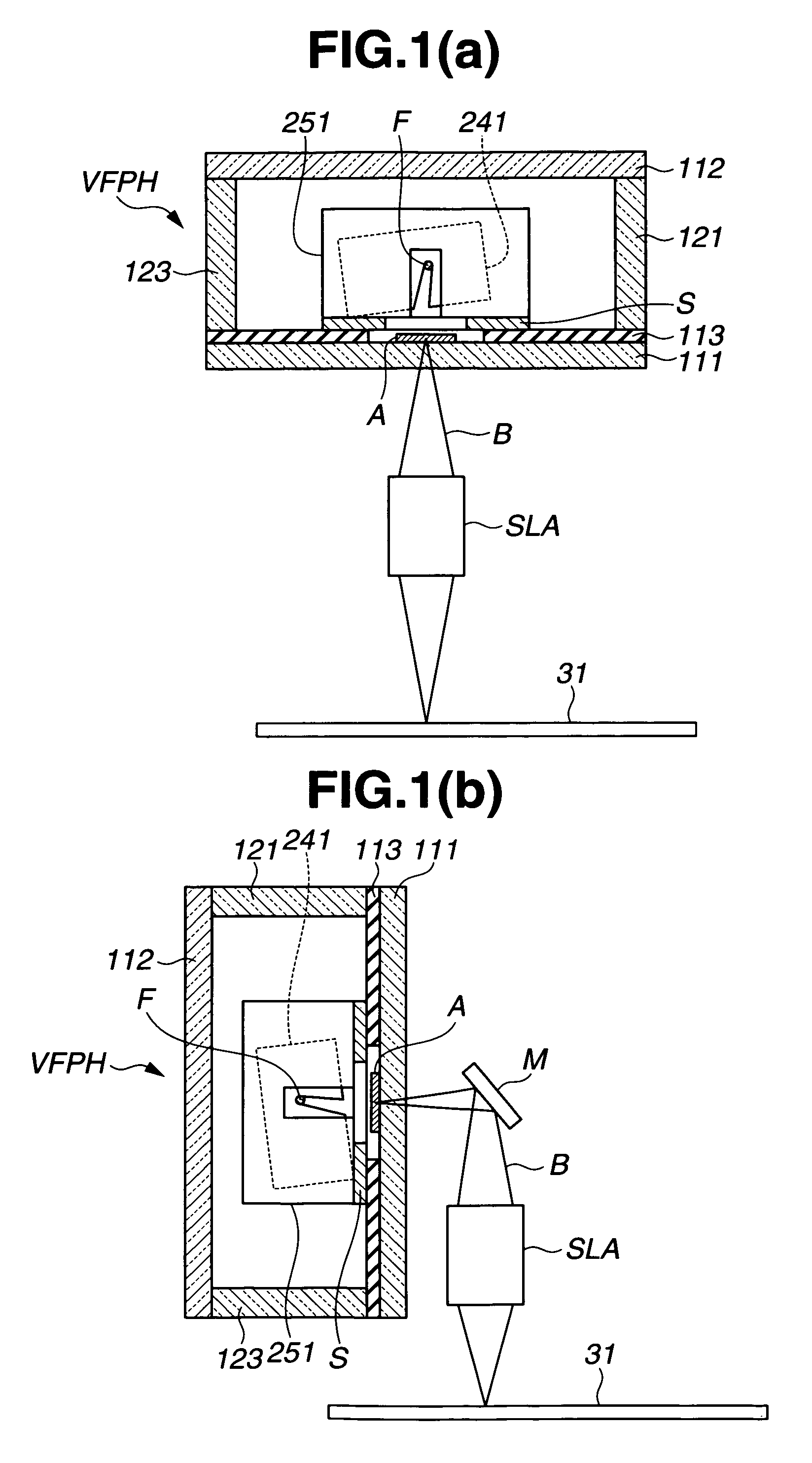
[0038]FIG. 1 is a schematic view illustrating an arrangement of a fluorescent luminous tube and an optical system member for an optical print head in an image forming device, according to an embodiment of the present invention. FIG. 1(a) shows an example of a fluorescent luminous tube disposed horizontally and FIG. 1(b) shows an example of a fluorescent luminous tube disposed vertically.

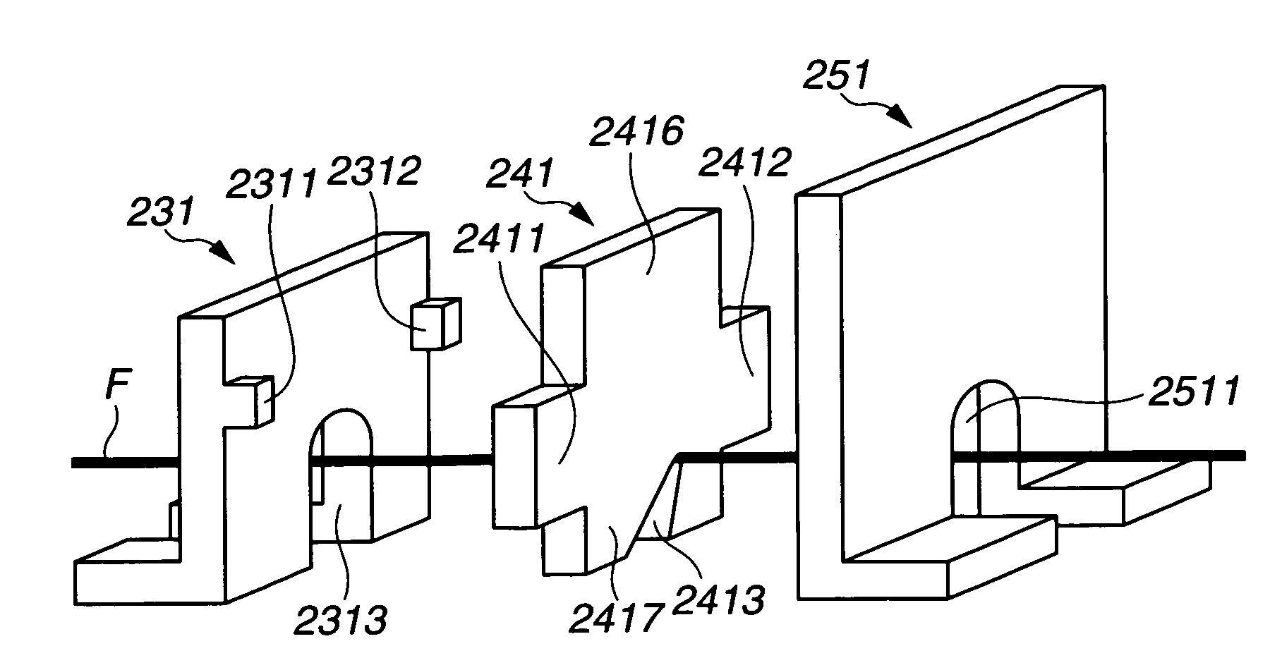
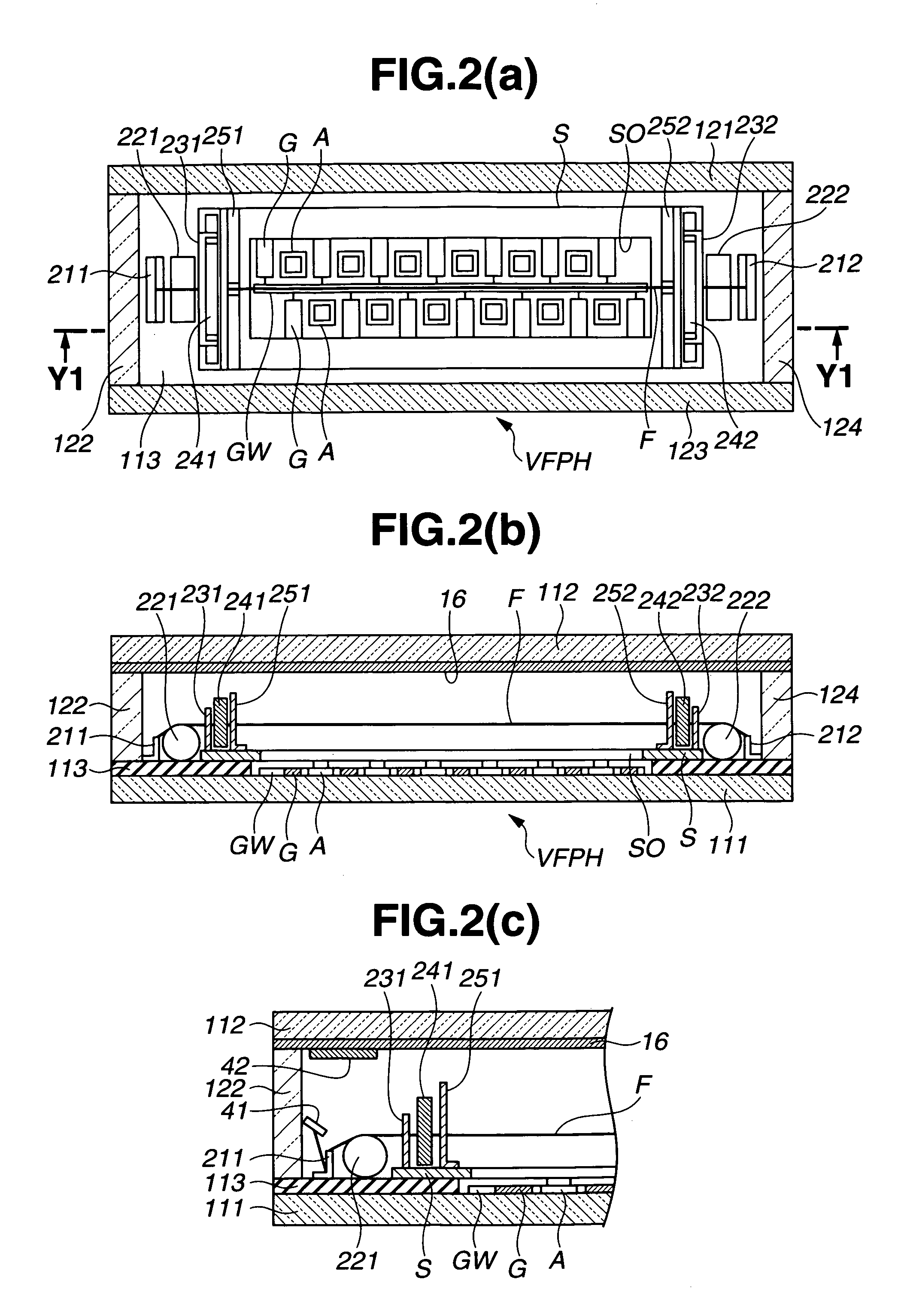
[0039]Referring to FIG. 1, a fluorescent luminous tube VFPH has an envelope, electrodes mounted inside the envelope, and others. In other words, the envelope includes a front substrate 111, a back substrate 112, and side members (side plates) 121, 123. An anode electrode A, on which a fluorescent substance is coated, an insulating layer 113, and a shielding electrode S are formed on the front substrate 111. A getter shieldin...


PUM


Abstract

In an electron tube including vibration absorbers for linear members such as filaments, a vibration absorbing means that is made of a vibration absorber with a large vibration absorption effect, has a simple configuration, and is attachable easily to filaments is provided. The vibration absorbing means is formed of a holder 231, a vibration absorber 241, and a getter shielding member 251. These three members are attached to a shielding electrode S overlying the front substrate 111 to dispose the vibration absorber 241 between the holder 231 and getter shielding member 251. The vibration absorber 241 is mounted to slide or rotate between the holder 231 and the getter shielding member 251. The vibration absorber 241 has an aperture 2413 in which the filament is engaged. The bottom (apex) of the aperture 2413 is formed eccentrically. The vibration absorber 241 is in line contact with the shielding electrode S, as shown in FIG. 3(c).

Description

CROSS REFERENCES TO RELATED APPLICATIONS[0001]This application claims the priority benefit of Japanese Patent Application No. 2004-011395 filed on Jan. 20, 2004.STATEMENT REGARDING FEDERALLY SPONSORED RESEARCH[0002]Not Applicable.BACKGROUND OF THE INVENTION[0003]1. Field of the Invention[0004]The present invention relates to electron tubes, such as fluorescent luminous tubes for optical print heads, fluorescent display tubes, flat cathode-ray tubes, and vacuum tubes, each in which cathode filaments, linear grids, linear getters, and linear dampers or linear spacers for them are provided. Particularly, the present invention relates to vibration absorbing means that can dampen linear members such as cathode filaments.[0005]2. Description of the Prior Art[0006]FIG. 9 is a schematic view illustrating a fluorescent luminous tube for an optical print head, which is an example of electron tubes provided with conventional filament vibration absorbing means (for example, refer to Japanese Pa...

Claims


Application Information

Patent Timeline
Patent Type & Authority Patents(United States)
IPC IPC(8): H01J1/18H01J1/88H01J29/04H01J31/00H01J31/12H01J31/15
CPCH01J1/18H01J1/88H01J31/126H01J31/15
Inventor SHIMIZU, YUKIHIKOSAITO, MASAOUEDA, KINYANAKAYAMA, MASAHIRONOGUCHI, KAZUSHIGE
Owner FUTABA CORPORATION
Why Eureka
Try Eureka