Compact optical detection system for a microfluidic device

a microfluidic device and optical detection system technology, applied in the field of detection optics, can solve the problems of inflexibility, cost, rigidity, and large size of current optical detection systems, and achieve the effect of avoiding the problem of alignment and focusing of existing optical detection systems

Active Publication Date: 2009-04-14
CAPLIPER LIFE SCI INC
View PDF14 Cites 140 Cited by
  • Summary
  • Abstract
  • Description
  • Claims
  • Application Information

AI Technical Summary

Benefits of technology

[0041]In practice, an optical detection system in accordance with the present invention offers a number of advantages over existing systems. For example, the lens layout allows excitation light to be delivered both axially, as in epifluorescence systems, or externally at an oblique angle. The high numerical aperture of the custom, fused-silica objective lens permits the use of a lower power and less expensive light source in the form of an LED. For example, a blue LED costs about $25, while a blue laser costs about $10,000. The lens system also allows the use of a single CCD, rather than multiple CCDs, for additional cost savings. In addition to being less expensive than typical optical detection systems, the described system is more compact. Because of the low cost and small size of systems in accordance with the invention, several LEDs of various colors may be incorporated into a system such as that seen in FIG. 1, thus providing built-in flexibility of excitation colors. Detection wavelengths may be set through software controls available to the user.

Problems solved by technology

Currently existing optical detection systems for microfluidic devices are large, expensive, and inflexible.
The size, expense, and rigidity of current optical detection systems result largely from such systems employing multiple high quality lasers for fluorescence excitation, along with multiple charge-coupled device (CCD) cameras for detection.
Alignment and focusing of existing optical detection systems also presents problems.
This can take several minutes for some microfluidic devices.
In addition, the fluorescent dye is typically flushed out of the channel after focusing, a time-consuming and sometimes difficult process.
Finally, the dye can be expensive and unstable, adding to the cost and complexity of the process.

Method used


Image

  • Compact optical detection system for a microfluidic device
  • Compact optical detection system for a microfluidic device
  • Compact optical detection system for a microfluidic device

Examples


Embodiment Construction

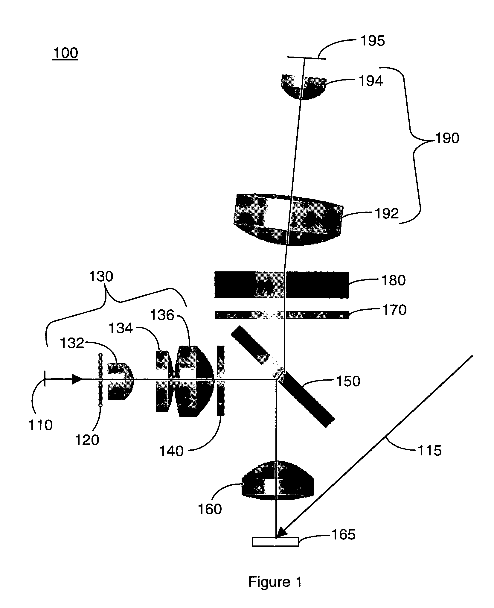
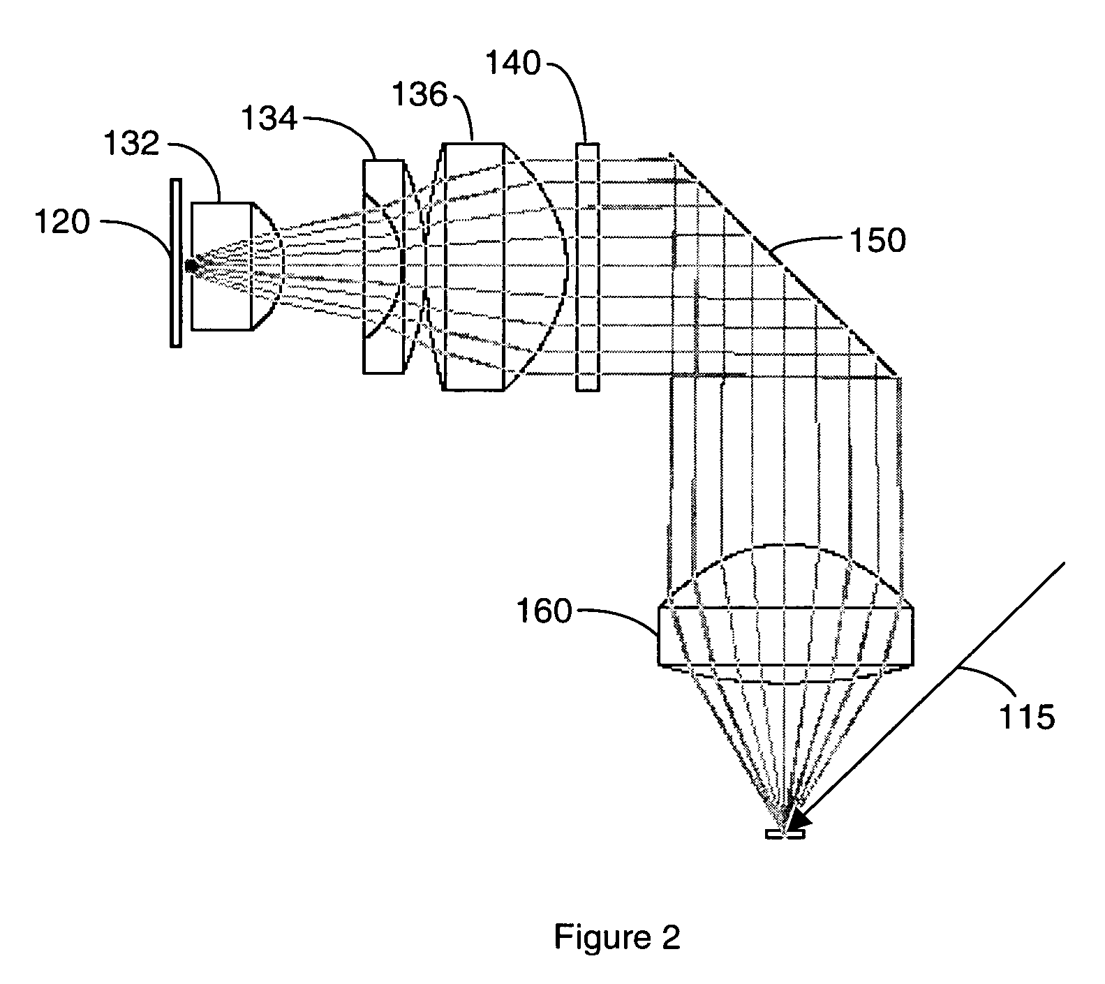
[0019]One aspect of the present invention is an optical detection system. One embodiment of the system, in accordance with the present invention, is illustrated in FIG. 1 at 100. In the present nonlimiting example, system 100 comprises an LED light source 110; a slit 120; a slit lens 130 comprising three slit lens elements 132, 134, and 136; an excitation bandpass filter 140; a beam splitter 150, an objective lens 160; a rejection filter 170; a diffraction grating 180; a CCD lens 190 comprising CCD lens elements 192 and 194; and a CCD array 195. A second light source, which may be either a laser or an LED, is indicated at 115. A microfluidic device is indicated at 165.

[0020]Slit 120 is back illuminated by LED 110. The LED may be used in place of or in addition to a laser light source, as will be explained below. The size, shape, wavelength, and power level of the LED may be varied. LEDs are currently available in various colors, including UV, blue, cyan, and green, representing emis...


PUM


Abstract

An optical detection system for a microfluidic device and a dry-focus microfluidic device compatible with the compact optical detection system are described. The system includes an LED; means for collimating light emitted by the LED; an aspherical, fused-silica objective lens; means for directing the collimated light through the objective onto a microfluidic device; and means for detecting a fluorescent signal emitted from the microfluidic device. The working distance between the objective and the device allows light from an external LED or laser to be brought in along a diagonal path to illuminate the microfluidic device. The dry-focus microfluidic device includes multiple channels and multiple closed optical alignment marks having curved walls. At least one of the channels is positioned between at least two of the marks. The marks are illuminated for alignment and focusing purposes by light brought in on a diagonal path from an external white LED.

Description

RELATED APPLICATION[0001]The present application claims priority to U.S. Provisional Patent Application Ser. No. 60 / 670,736, filed Apr. 12, 2005, entitled “Optical Detection for Microfluidic Devices,” which is hereby incorporated by reference for all purposes as if set forth herein verbatim.TECHNICAL FIELD[0002]This invention relates generally to the field of detection optics. More specifically, the invention relates to a compact optical system for detecting fluorescent signals as well as a dry-focus microfluidic device compatible with the compact optical detection system.BACKGROUND OF THE INVENTION[0003]Currently existing optical detection systems for microfluidic devices are large, expensive, and inflexible. In existing microfluidic device instrumentation, the optical detection system is the costliest subsystem. The size, expense, and rigidity of current optical detection systems result largely from such systems employing multiple high quality lasers for fluorescence excitation, a...

Claims


Application Information

Patent Timeline
Patent Type & Authority Patents(United States)
IPC IPC(8): G01B11/00
CPCB01L3/502715G01B11/002G01N21/645B01L3/5027B01L2200/025B01L2300/0816G01N2021/0162G01N2021/6419G01N2021/6421G01N2021/6478G01N2201/0627G02B21/16
Inventor RULISON, AARONWOLK, JEFFREY A.LEE, ERNEST C.W.SLATER, MICHAELJENSEN, MORTEN J.
Owner CAPLIPER LIFE SCI INC
Why Eureka
Try Eureka