Hybrid electric vehicle chassis with removable battery module

a hybrid electric vehicle and battery module technology, applied in the direction of charging stations, electric propulsion mounting, transportation and packaging, etc., can solve the problems of limiting vehicle performance and vehicle range, increasing vehicle weight, and battery or battery bank not being normally removed from the vehicle, so as to reduce vehicle weight, increase vehicle range, and easy to slide into and ou

Inactive Publication Date: 2009-04-21
CHANEY GEORGE T
View PDF4 Cites 85 Cited by
  • Summary
  • Abstract
  • Description
  • Claims
  • Application Information

AI Technical Summary

Benefits of technology

[0012]It is therefore an object of the present invention to provide a chassis defining a battery module compartment that receives a battery module therein as an integral part, thereby reducing vehicle weight and increasing vehicle range.
[0013]It is another object of the present invention to provide a battery module that easily slides into and out from the battery module compartment.

Problems solved by technology

Electrical powered vehicles have been available for many years but have never been widely accepted for use due to their limited range, however, hybrid-electric powered vehicles have been gaining popularity.
Often, the battery or bank of batteries requires a separate compartment and mounting assembly, which greatly increases vehicle weight and, thus, limits vehicle performance and vehicle range.
The battery or bank of batteries is not normally removable from the vehicle.

Method used


Image

  • Hybrid electric vehicle chassis with removable battery module
  • Hybrid electric vehicle chassis with removable battery module
  • Hybrid electric vehicle chassis with removable battery module

Examples


second embodiment

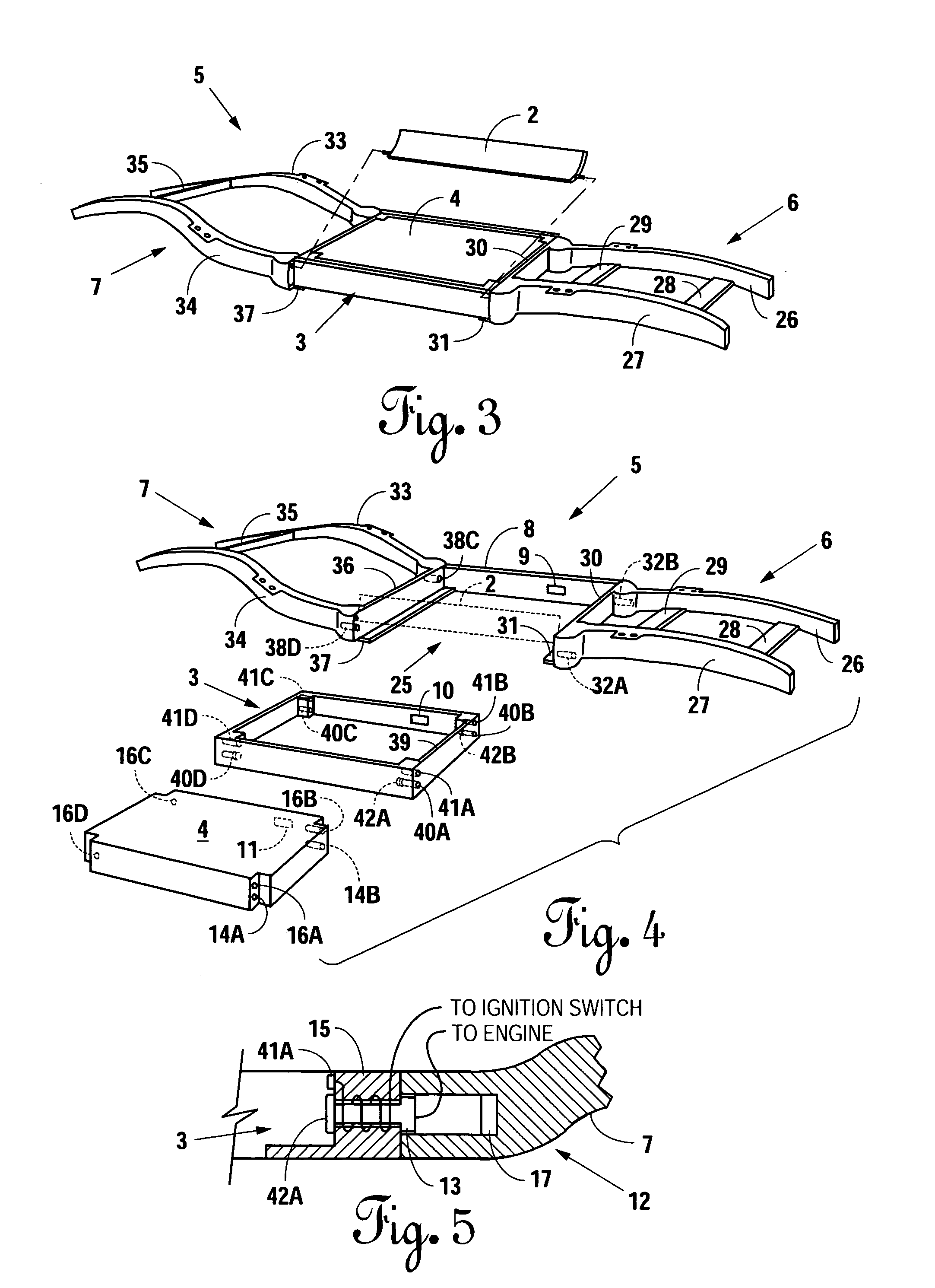
[0056]When a vehicle operator uses the key 20 to move the ignition switch 22 to an off position, the coils 15 de-energize, resulting in the natural magnets drawing a respective bolt 13 into a respective cylindrical cavity 32A and B and 38C and D, thereby unlocking the battery module 3 and removing power from the electric motor 65. The hybrid-electric powered vehicle 1 of this second embodiment de-energizes the coils and breaks the circuit to isolate the battery 4, thereby providing maximum conservation of the battery 4. The internal combustion engine 18 is also disabled when the ignition switch 22 is in the off position, thereby ceasing the generation of power by the generator 71.

[0057]The hybrid-electric powered vehicle 1 may further include an electrical input 112 having a first terminal 97 and a second terminal 98. The electrical input 112 may be disposed at an accessible location, and suitably mounted to the chassis 5 or 50. The electrical input 112 may be any form of electrical...

first embodiment

[0069]As shown in FIG. 9a-9b, the electrical driving system 124B includes an electric motor 65, a control system 144, an on-board battery compartment 67, and a removable battery module 3. The electric motor 65 and the removable battery module 3 are identical in form and function to the electric motor 65 and the removable battery module 3 disclosed in the The control system 144 is a microprocessor based control system, and includes a controller 145. The control system 144 is in electrical communication with the electric motor 65 through a motor lead 155. A lead 85 completes the electrical path from the positive terminal of the removable battery module 3 to the variable power transfer device 19, and a lead 86 completes the electrical path between variable power transfer device 19 and the electric motor 65.

[0070]The control system 144 is in electrical communication with a positive terminal of the on-board battery compartment 67 through a first lead 150, and the control system 144 is i...


PUM


Abstract

A hybrid-electric powered vehicle includes a chassis defining a battery module compartment and a battery module insertable into the battery module compartment. The hybrid-electric powered vehicle includes provisions for recharging a battery module compartment of the hybrid-electric powered vehicle when the electric drive system is operated. The battery module may further be charged by external sources while the battery module is disposed within the chassis, removed from the chassis, and by internal sources when the hybrid-electric powered vehicle is decelerating. In a second embodiment, the hybrid-electric powered vehicle further includes an on-board battery compartment, and a control system that regulates the distribution of power from the electrical power sources to the electric motor. The control system may utilize either the battery module or the on-board battery compartment, or the control system may place the two electrical power sources in series or in parallel, as required to meet electrical power demands.

Description

CROSS-REFERENCE TO RELATED APPLICATIONS[0001]This application is a continuation-in-part of application Ser. No. 10 / 645,025, filed Aug. 21, 2003, now U.S. Pat. No. 7,201,384 which was a divisional of Ser. No. 09 / 610,908, filed Jul. 6, 2000, now U.S. Pat. No. 6,631,775 B1, issued Oct. 14, 2003.BACKGROUND OF THE INVENTION[0002]1. Field of the Invention[0003]The present invention relates to hybrid-electric powered vehicles, and, more particularly, but not by way of limitation, to a hybrid-electric powered vehicle chassis having a removable battery module.[0004]2. Description of the Related Art[0005]Electrical powered vehicles have been available for many years but have never been widely accepted for use due to their limited range, however, hybrid-electric powered vehicles have been gaining popularity. A hybrid-electric powered vehicle typically includes an internal combustion engine, as well as an electric motor and drive train supported on a frame and enclosed in a body. In addition to...

Claims


Application Information

Patent Timeline
Patent Type & Authority Patents(United States)
IPC IPC(8): B60R16/04B60K1/00B60K1/04B60K6/28B60K6/405
CPCB60K1/04B60K6/28B60K6/405B60K2001/0494B60K2001/0438B60K2001/0461B60L53/80Y02T10/70Y02T10/7072
Inventor CHANEY, GEORGE T.
Owner CHANEY GEORGE T
Why Eureka
Try Eureka