Combined jitter and multiplexing systems and methods

a technology of video data and jitter support, applied in the field of system and method for transmitting data, can solve the problems of reducing the rate of video data, reducing the quality of output video, and often reducing the video quality of end-users, so as to improve the look ahead performance and jitter support, improve the look ahead window size, and improve the effect of performan

Active Publication Date: 2009-05-05
CISCO TECH INC
View PDF44 Cites 61 Cited by
  • Summary
  • Abstract
  • Description
  • Claims
  • Application Information

AI Technical Summary

Benefits of technology

[0007]The present invention provides improved systems and methods for processing and transmitting data included in packets with jitter. In one aspect of the present invention, a jitter buffer and buffer scanned by a look ahead window are implemented as a combined buffer. When the next processing stage after jitter buffering implements a look ahead window, such as multiplexing, statistical rate re-multiplexing or any other processing that uses a look ahead approach to improve performance, the present invention permits flexible buffering techniques to improve look ahead performance and jitter support. In this case, the combined buffer varies look ahead window and multiplexer performance based on the current jitter of the data arriving in the buffer. More specifically, the flexible buffering techniques flexibly adapt the size of the look ahead window based on the amount of jitter present. When jitter is are low, the size of the look ahead window is increased. Since most multiplexers that implement a look ahead window benefit from a larger look ahead window, and the average network jitter in the packets is typically far less than the maximum network jitter designed into a jitter buffer, a combined buffer as described herein allows a larger look ahead window and improved multiplexer performance. As mentioned previously, improved multiplexer performance may lead to less re-encoding or more intelligent re-encoding and bit rate reduction for video data transmission applications, leading to improved decoded output video quality.

Problems solved by technology

One problem with delivering real-time compressed video bitstreams over a given bandwidth channel is matching the available bandwidth to the compressed bit rate of the data being transmitted.
Rate reduction often diminishes end-user video quality.
However, many conventional transmission systems produce excessive rate reduction, leading to diminished output video quality.

Method used


Image

  • Combined jitter and multiplexing systems and methods
  • Combined jitter and multiplexing systems and methods
  • Combined jitter and multiplexing systems and methods

Examples


Embodiment Construction

[0019]The present invention will now be described in detail with reference to a few preferred embodiments thereof as illustrated in the accompanying drawings. In the following description, numerous specific details are set forth in order to provide a thorough understanding of the present invention. It will be apparent, however, to one skilled in the art, that the present invention may be practiced without some or all of these specific details. In some instances, well known process steps and / or structures have not been described in detail in order to not unnecessarily obscure the present invention.

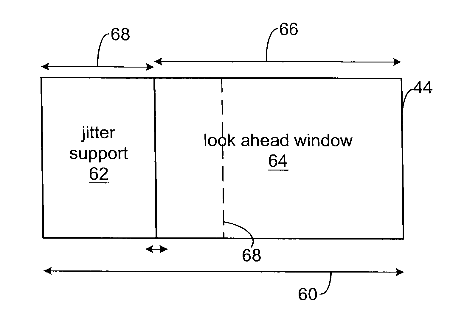
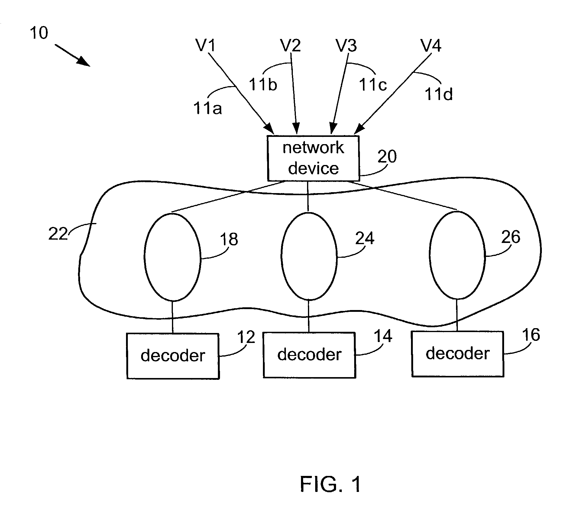
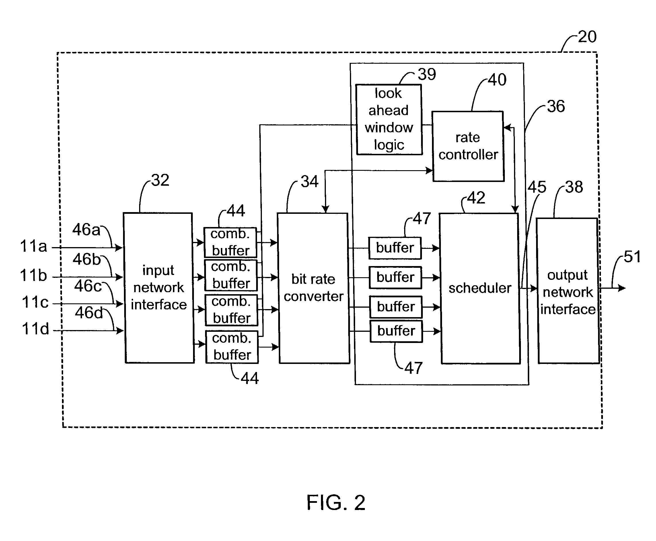
[0020]In one embodiment, systems and methods of the present invention include a multiplexer or re-multiplexer that uses a look ahead window to determine future demands of the various bitstreams being multiplexed. The look ahead window allows the multiplexer or re-multiplexer to make better decisions regarding allocating bandwidth for different bitstream or channels and for determining when ...


PUM


Abstract

Described herein are systems and methods for processing and transmitting data included in packets with jitter. The systems and methods combine a jitter buffer and a buffer scanned by a look ahead window as a combined buffer. The combined buffer varies look ahead window and performance of a process that uses the look ahead window based on the current jitter support in the buffer. More specifically, the flexible buffering techniques flexibly adapt the size of the look ahead window based on the amount of buffer space used for jitter support. When jitter support requirements are low, the size of the look ahead window is increased. When the look ahead window is implemented with a multiplexer, the multiplexer may benefit from a larger look ahead window and improve multiplexer performance. Improved multiplexer performance may lead to less or more intelligent re-encoding and bit rate reduction for video data transmission applications, leading to improved decoded output video quality.

Description

BACKGROUND OF THE INVENTION[0001]The present invention relates generally to systems and methods for transmitting data. More specifically, the present invention relates to improved jitter processing and multiplexing of video data.[0002]There are presently a variety of different communication channels for transmitting or transporting video data. For example, communication channels such as coaxial cable distribution networks, digital subscriber loop (DSL) access networks, ATM networks, satellite, terrestrial, or wireless digital transmission facilities are all well known. Many standards have been developed for transmitting data on the communication channels. For the purposes herein, a channel is defined broadly as a connection facility to convey properly formatted digital information from one point to another. A channel includes some or all of the following elements: 1) physical devices that generate and receive the signals (modulator / demodulator); 2) medium that carries the actual sig...

Claims


Application Information

Patent Timeline
Patent Type & Authority Patents(United States)
IPC IPC(8): H04L12/28
CPCH04N21/23406H04N21/2368H04N21/4305H04N21/4341H04N21/44004H04L12/2801
Inventor RAMAKRISHNAN, SANGEETA
Owner CISCO TECH INC
Why Eureka
Try Eureka