Advanced pulsed plasma thruster with high electromagnetic thrust

a pulsed plasma and thruster technology, applied in the direction of plasma technique, electrical apparatus, plasma, etc., can solve the problems of phenomenologically more complex electric thrusters, significantly more difficult analytical and technologically difficult to implement, and the addition of a supersonic nozzle usually provides little to no benefi

Active Publication Date: 2009-05-12
CU AEROSPACE
View PDF1 Cites 21 Cited by
  • Summary
  • Abstract
  • Description
  • Claims
  • Application Information

AI Technical Summary

Benefits of technology

[0023]The thruster may also include an insulating member that separates the central electrode from the annular electrode so as to maintain a non-conductive path to protect against electrodes shorting as a result of carbon deposits on the cavity surfaces.

Problems solved by technology

In comparison with electrothermal thrusters, electromagnetic thrusters are phenomenologically more complex.
They are also considerably more difficult to model analytically and technologically more difficult to implement.
In the case of an electromagnetic pulsed plasma thruster, the addition of a supersonic nozzle usually provides little to no benefit since the low chamber pressures do not facilitate significant supersonic gas expansion.

Method used


Image

  • Advanced pulsed plasma thruster with high electromagnetic thrust
  • Advanced pulsed plasma thruster with high electromagnetic thrust
  • Advanced pulsed plasma thruster with high electromagnetic thrust

Examples


Embodiment Construction

[0033]While the invention is susceptible to embodiments in many different forms, the preferred embodiments of the present invention are shown in the drawings (FIG. 3-7) and will be described in detail herein. It should be understood, however, that the present disclosure is to be considered an exemplification of the principles of the invention and is not intended to limit the spirit or scope of the invention and / or the embodiments illustrated. It is to be understood that no limitation with respect to the specific methods and apparatus illustrated herein is intended or should be inferred.

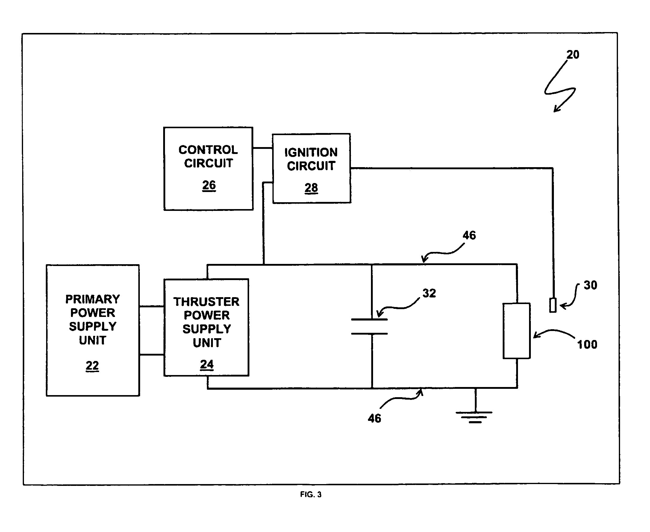
[0034]A schematic of a pulsed thruster system 20, in accordance to the present invention, is shown in FIG. 3. The system 20 includes a primary power supply unit 22, a thruster power supply unit 24, a control circuit 26, an ignition circuit 28, a spark generating device 30, a capacitor 32, and a thruster 100. The primary power supply 22 is coupled to the thruster power supply 24, which in turn is coupl...


PUM


Abstract

A pulsed plasma thruster provides for an advanced lightweight design with solid propellant and predominately electromagnetic thrust in a coaxial geometry. Electromagnetic forces are generated in a plasma by current flowing from a small central electrode to an electrically conducting diverging nozzle electrode. The thruster employs a series of electric current pulses of limited duration and varying frequency between the pair of electrodes creating a series of electric arcs. The electric arcs pass over a propellant surface located between the electrodes, forming a plasma, which is then exhausted from the device to produce thrust. The thruster maintains a low plasma resistance and cavity pressure, which in turn yields strong electromagnetic body forces, resulting in a high efficiency and consistent pulse-to-pulse performance.

Description

RELATED APPLICATIONS[0001]The present invention is a Continuation In Part of U.S. patent application Ser. No. 10 / 457,659 filed on Jun. 9, 2003, which claims priority to Provisional Application Ser. No. 60 / 389,080 filed Jun. 14, 2002.FIELD OF THE INVENTION[0002]The present invention is directed to a subset of electric propulsion, pulsed plasma thrusters, for maneuvering of a mass in microgravity.BACKGROUND OF THE INVENTION[0003]A pulsed plasma thruster is typically used to maneuver spacecraft and satellites in microgravity. The thruster employs a series of electric current pulses of limited duration and varying frequency between a pair of electrodes creating a series of electric arcs. The electric arcs pass over the surface of a propellant, increasing the surface temperature of the propellant, thereby forming an ionized gas, known as a plasma. The plasma is then exhausted from the device to produce thrust.[0004]The two primary classifications of pulsed plasma thrusters are electrothe...

Claims


Application Information

Patent Timeline
Patent Type & Authority Patents(United States)
IPC IPC(8): F03H1/00
CPCF03H1/0087
Inventor BURTON, RODNEYBENAVIDES, GABRIELLAYSTROM, JULIA
Owner CU AEROSPACE
Why Eureka
Try Eureka