Drill, such as a twist drill

a twist drill and drill bit technology, applied in the field of drill bit, can solve the problems of not being able to produce a hole bottom, milling cutter, and not being able to drill such blind holes with a conventional twist drill bit, and achieve the effect of shortening the machining time for the production of blind holes, substantial economic efficiency, and shortening the process tim

Active Publication Date: 2009-05-12
KENNAMETAL INC
View PDF21 Cites 20 Cited by
  • Summary
  • Abstract
  • Description
  • Claims
  • Application Information

AI Technical Summary

Benefits of technology

[0013]One advantage of this drill designed as a plane-bottom drill is the fact that for the production of, for example, blind holes with a completely planar hole bottom, at least approximately the same cutting parameters and the same process and drilling times are achieved as with a conventional twist drill with a conical drill tip. Thus, as compared with conventional slot mills, which usually have only one front edge and a large web diameter, clearly shorter process times are achieved, i.e. the machining time for the production of a blind hole is clearly shorter.
[0030]Also, for the sake of an appropriate guidance of the drill, it is provided that each main cutting edge merges, over a corner cutting edge which is rounded and also possibly chamfered, into a respective minor cutting edge extending along the chip flute. This chamfered or rounded design of the corner cutting edge provides for a self-centering of the drill, such as when spot-drilling. To keep the resulting roundness or chamfer of the bottom of the drilled hole as small as possible, the height of the roundness or of the chamfer, parallel to the longitudinal axis of the drill, is approx. 0.15 to 0.80 mm for a drill diameter of 3 to 30 mm.

Problems solved by technology

It is not possible to drill such blind holes by means of a conventional twist drill, due to the inclination of the main cutting edges to each other at an acute angle.
Due to the projecting primary cutting edge, this drill is also not able to produce a hole bottom with a completely planar surface.
Such a milling cutter is, however, not suitable for drilling operations due to the fact that it has no cutting edge in the center area, and thus a purely rotational movement will not remove any chips in the center area.
In this way, the forces acting upon the drill are symmetrically distributed, so that during the drilling operation, the drill is subjected to only slight lateral forces, which would negatively influence the geometry of the drill-hole.
At the same time, however, due to the small inclination, the width must not be too large, as otherwise the clearance for the chip to be removed would not be sufficient.

Method used


Image

  • Drill, such as a twist drill
  • Drill, such as a twist drill
  • Drill, such as a twist drill

Examples


Embodiment Construction

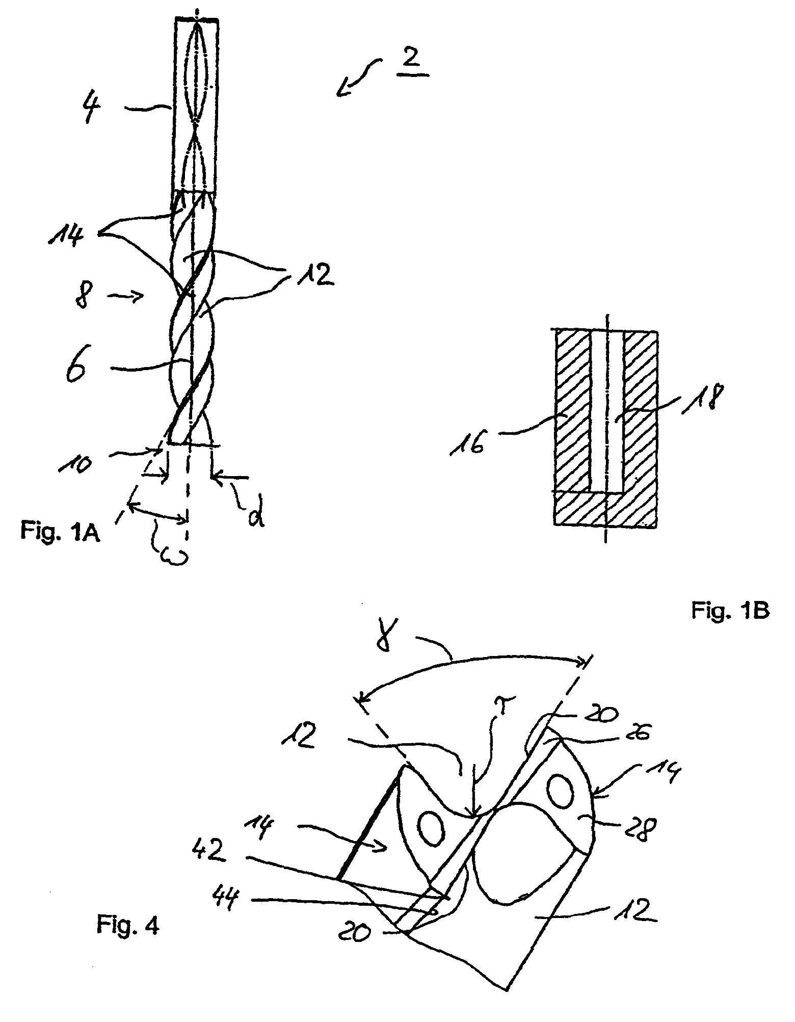
[0045]The drill 2, designed as a twist drill according to FIG. 1A, comprises a shank 4, a body 8 adjacent to it along a longitudinal axis 6 of the drill, the front end of the body 8 being provided with a drill front 10. Helically extending chip spaces or chip flutes 12, with a web 14 each being formed between them, are formed into the body 8. The chip flutes 12 are oriented at a helix angle ω relative to the longitudinal axis 6. The drill has a drill diameter d which slightly decreases in the direction of the shank 4.

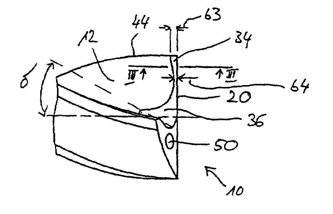
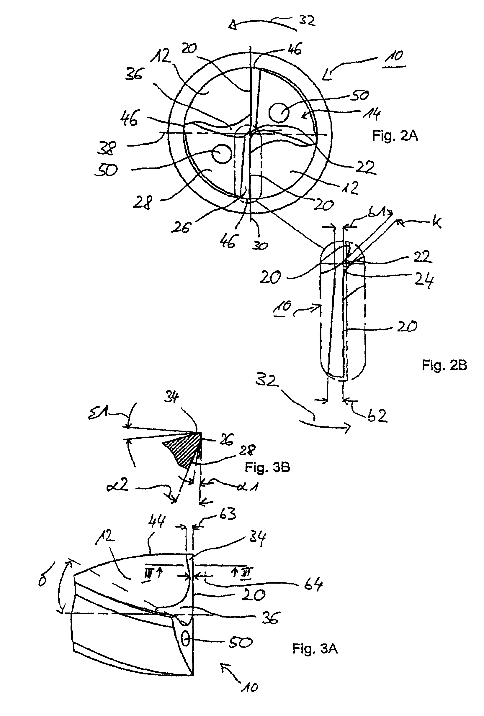
[0046]FIG. 1A shows clearly that the drill front 10 is of a virtually completely planar design and lies in a plane which is essentially perpendicular to the longitudinal axis 6. With such a drill 2, a blind hole 18 with a virtually completely planar bottom can be produced in a workpiece 16, as is apparent from FIG. 1B.

[0047]The virtually completely planar design of the drill front 10 also enables an easy spot-drilling even on curved surfaces because due to the absence o...


PUM

PropertyMeasurementUnit
diametersaaaaaaaaaa
diametersaaaaaaaaaa
diametersaaaaaaaaaa

Abstract

A drill bit, such as a twist drill, having a body equipped with flutes, as well as a drill bit face that includes two main cutting edges that merge together. In order to drill a blind hole, such as with a level drilled bottom, the main cutting edge forms a continuous cutting edge that runs in a plane perpendicular to the drill bit's longitudinal axis. The main cutting edges, with respect to a cutting direction, are arranged behind a center line lying in the plane which is perpendicular to the longitudinal axis of the drill and extending through the center of the drill as well as in the direction of the main cutting edges.

Description

CONTINUING APPLICATION DATA[0001]This application is a Continuation-In-Part application of International Patent Application No. PCT / EP2005 / 005234, filed on May 13, 2005, which claims priority from both Federal Republic of Germany Patent Application No. 20 2004 008 700.6, filed on May 28, 2004, and Federal Republic of Germany Patent Application No. 20 2004 010 977.8, filed on Jul. 14, 2004. International Patent Application No. PCT / EP2005 / 005234 was pending as of the filing date of this application. The United States was an elected state in International Patent Application No. PCT / EP2005 / 005234.BACKGROUND[0002]1. Technical Field[0003]The present application relates to a drill, such as a twist drill, having a body provided with chip flutes as well as a drill front provided with at least two main cutting edges merging into each other.[0004]2. Background Information[0005]According to standard DIN ISO 5419, such a twist drill comprises a drill tip, herein referred to as drill front, which...

Claims


Application Information

Patent Timeline
Patent Type & Authority Patents(United States)
IPC IPC(8): B23B51/02B23B51/00
CPCB23B51/02Y10T408/9097Y10T408/909B23B2251/14B23B51/00
Inventor REINHARDT, WERNERKRIEG, TILO
Owner KENNAMETAL INC
Why Eureka
Try Eureka