Low-complexity active transconductance circuit

a transconductance circuit and low-complexity technology, applied in the field of active electronic circuits, can solve the problems of high output impedance, relatively low circuit complexity, and large circuit area, and achieve the effects of reducing circuit area requirement, reducing circuit complexity, and reducing supply curren

Inactive Publication Date: 2009-05-12
DIALOG SEMICONDUCTOR BV
View PDF8 Cites 17 Cited by
  • Summary
  • Abstract
  • Description
  • Claims
  • Application Information

AI Technical Summary

Benefits of technology

[0007]It is desirable in view of the foregoing to provide an active transconductance circuit that can meet conventional performance specifications, but at a lower supply current, and / or with lower circuit complexity, and / or with a lower circuit area requirement.

Problems solved by technology

Such an active transconductance circuit is highly linear, has a high output impedance, requires relatively low supply current, relatively low circuit complexity and a relatively small amount of circuit area.

Method used


Image

  • Low-complexity active transconductance circuit
  • Low-complexity active transconductance circuit
  • Low-complexity active transconductance circuit

Examples


Embodiment Construction

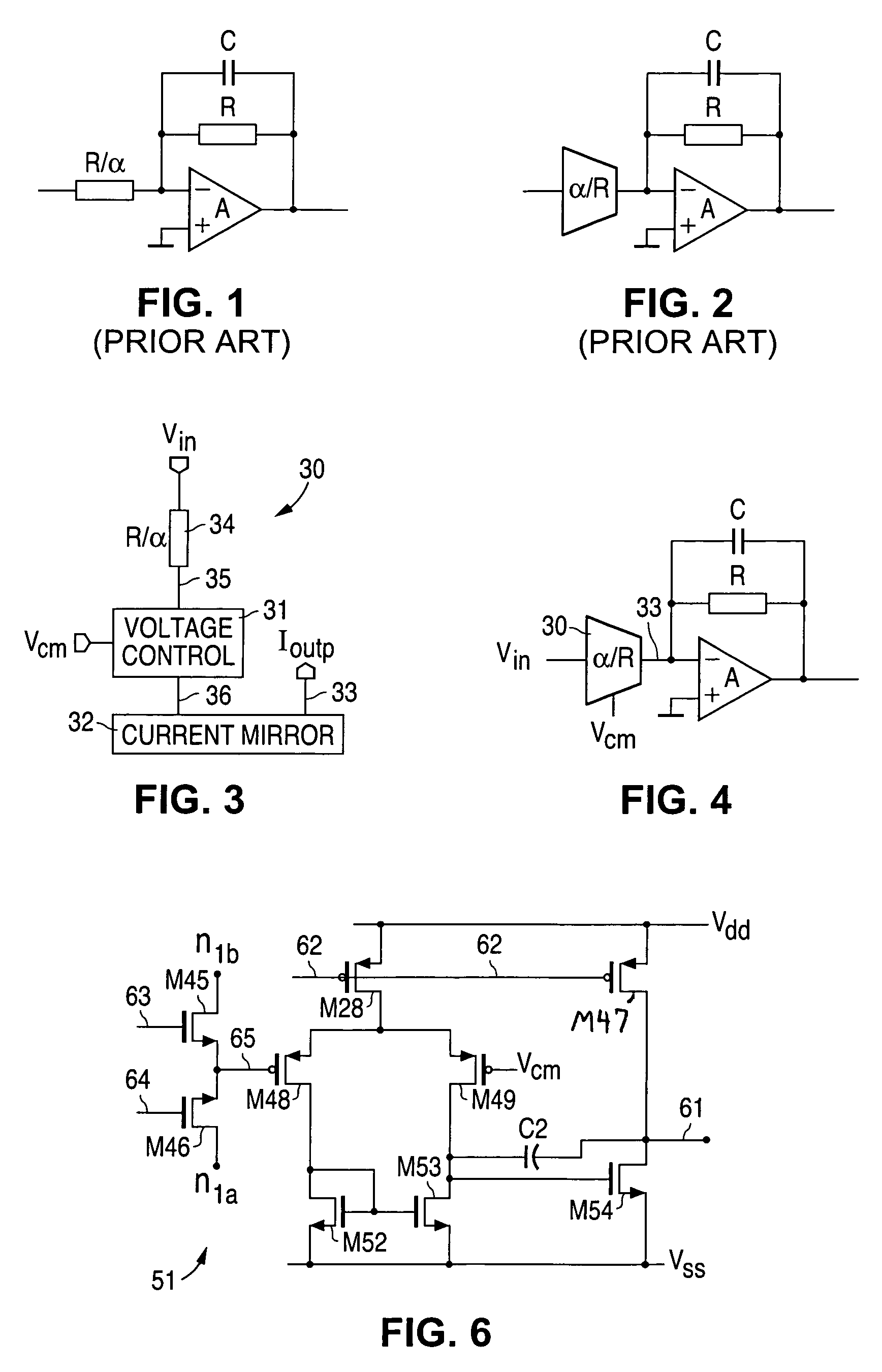
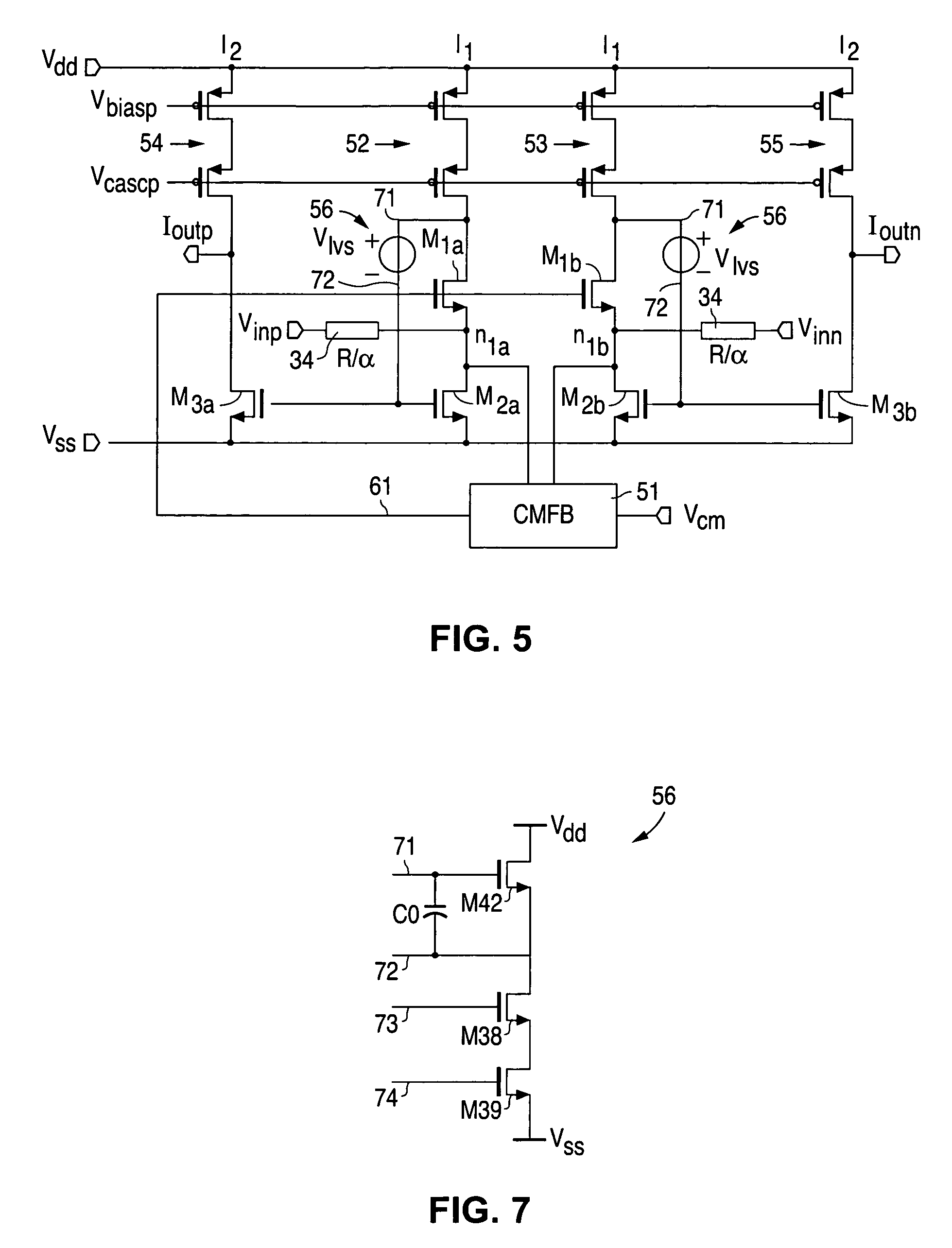
[0017]FIGS. 1 through 7, discussed herein, and the various embodiments used to describe the principles of the present invention in this patent document are by way of illustration only and should not be construed in any way to limit the scope of the invention. Those skilled in the art will understand that the principles of the present invention may be implemented in any suitably arranged processing system.

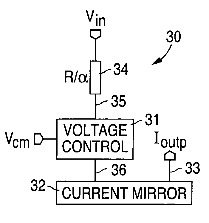
[0018]FIG. 3 diagrammatically illustrates a transconductor according to exemplary embodiments of the invention. A resistor 34 is applied directly at the voltage input Vin. This resistor 34, having a resistance value of R / α (see also FIGS. 1 and 2) functions as a linear voltage-to-current converter. A voltage control circuit 31 is connected to the resistor 34 at a terminal 35 thereof opposite the voltage input terminal. The voltage control circuit 31 operates to maintain the resistor terminal 35 generally fixed at a common-mode voltage, which can be considered as a virtual ground. Th...


PUM


Abstract

An active transconductance is provided by converting an input voltage into a current, and providing the current to a node which is maintained at a generally fixed voltage. Current is mirrored from the fixed voltage node to an output node. Such an active transconductance circuit can meet conventional performance specifications, but at a lower supply current, and / or with lower circuit complexity, and / or with a lower circuit area requirement.

Description

TECHNICAL FIELD OF THE INVENTION[0001]The invention relates generally to active electronic circuits and, more particularly, to active transconductance circuits.BACKGROUND OF THE INVENTION[0002]Active transconductance circuits are generally characterized by high linearity and high output impedance. These characteristics are desirable at the input of an active RC filter, for example, a radio receiver channel-select filter.[0003]FIG. 1 diagrammatically illustrates an example of a conventional active RC low-pass filter. If the operational amplifier A is assumed to be ideal (infinite DC gain and bandwidth), then the filter response is entirely determined by the resistor ratio (α) and the RC product. However, a non-ideal operational amplifier will affect the filter response. For a variable gain implementation, the filter response even depends upon the gain setting.[0004]FIG. 2 diagrammatically illustrates a conventional solution which reduces the non-ideal operational amplifier's impact o...

Claims


Application Information

Patent Timeline
Patent Type & Authority Patents(United States)
IPC IPC(8): H03K5/00H02M11/00
CPCH03F3/45179H03F3/45475H03F3/45632H03F2203/45136H03F2203/45166H03F2203/45306H03F2203/45354H03F2203/45526H03F2203/45594H03F2203/45674
Inventor MULDERS, ADRIANUS GERARDUS
Owner DIALOG SEMICONDUCTOR BV
Why Eureka
Try Eureka