Methods and systems for cooling a chromatographic column

a technology of chromatographic column and cooling system, which is applied in the direction of ion exchangers, separation processes, instruments, etc., can solve the problems of significant stationary phase bleed of columns, significant and unproductive portion of the total time needed to perform sequence analysis, and gas being hostile to columns, so as to reduce the effect of stationary phase bleed and rapid cooling of columns

Inactive Publication Date: 2009-05-19
PERKINELMER HEALTH SCIENCES INC
View PDF16 Cites 21 Cited by
  • Summary
  • Abstract
  • Description
  • Claims
  • Application Information

AI Technical Summary

Benefits of technology

[0009]The present teachings include systems and methods for cooling a chromatographic column by controlling the flow of fluid into a chromatographic column during cooldown such that detector gases drawn back into the column are reduced during a decrease of the column temperature. Further, systems and methods are provided for controlling the flow of fluid into a chromatographic column that permit rapid cooling of the column. Additionally, systems and methods are provided for controlling the flow rate of a fluid into a chromatographic column that does not require an additional carrier gas supply. Also, systems and methods are provided for controlling a chromatographic column so as to reduce the effects of stationary phase bleed.

Problems solved by technology

This cool-down step is a part of the analytical cycle, but it can represent a significant and unproductive portion of the total time needed to perform a sequence of analyses.
Because the column outlet typically resides inside a detector, this vacuum will draw gases that are inside the detector back into the column during such rapid cooling, and these gases may be hostile to the column.
However, this approach requires the use of an additional carrier gas supply, which is undesirable due to the concomitant extra cost and complexity necessary to install and operate an extra gas supply.
Additionally, some columns generate significant stationary phase bleed when operated at temperatures close to their specified limit.

Method used


Image

  • Methods and systems for cooling a chromatographic column
  • Methods and systems for cooling a chromatographic column
  • Methods and systems for cooling a chromatographic column

Examples


Embodiment Construction

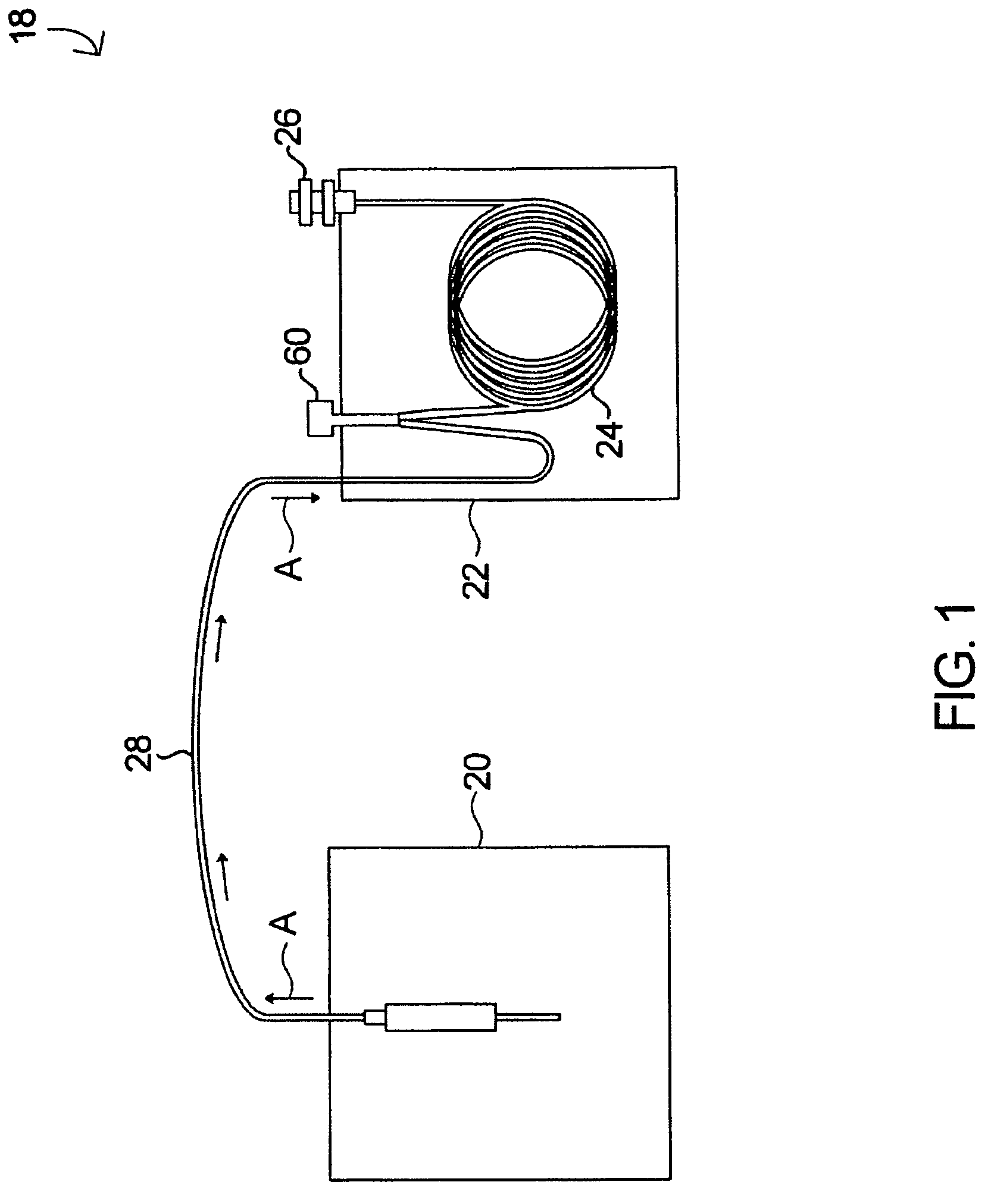
[0035]The basic components of one embodiment of a system for preventing the ingress of detector gases into a chromatographic column in accordance with the invention are illustrated in FIG. 1. As used in the description, the terms “top,”“bottom,”“above,”“below,”“over,”“under,”“above,”“beneath,”“on top,”“underneath,”“up,”“down,”“upper,”“lower,”“front,”“rear,”“back,”“forward” and “backward” refer to the objects referenced when in the orientation illustrated in the drawings, which orientation is not necessary for achieving the objects of the invention.

[0036]The system 18 includes a sampling device 20, such as a thermal desorption unit or a headspace sampler, in which a sample vessel, such as a sorbent tube, is disposed. The system 18 also includes a chromatographic oven 22, which, in certain embodiments, is temperature-programmable. A chromatographic column 24 is at least partially disposed in the oven 22, and the outlet end of the column 24 is connected to a detector 26. The sampling d...


PUM


Abstract

Systems and methods for cooling a chromatographic column is disclosed generally, comprising heating a chromatographic column, supplying fluid into the column via the inlet end of the column at an inlet pressure, decreasing the temperature of the column, thereby causing the fluid in the column to contract, and controlling the fluid in the column such that the rate at which the fluid in the column contracts does not exceed the flow rate of the fluid supplied to the column. In certain embodiments, the rate of change of the volume of the fluid in the column as the column temperature decreases is modeled, and the rate of contraction of the gas in the column is estimated therefrom. In some embodiments, the column temperature and / or inlet pressure are controlled by a programmable chromatographic oven.

Description

CROSS-REFERENCE TO RELATED APPLICATIONS[0001]This patent application claims the benefit of, under Title 35, United States Code, Section 119(e), U.S. Provisional Patent Application Ser. No. 60 / 595,191, filed Jun. 14, 2005, and U.S. Provisional Patent Application Ser. No. 60 / 595,679, filed Jul. 27, 2005, the contents of each of which are herein incorporated by reference in their entirety.FIELD OF THE INVENTION[0002]The present invention relates to systems and methods for cooling a chromatographic column by reducing the ingress of detector gases into a chromatographic column as the column is cooled. More specifically, the invention relates to a method of controlling the fluid flowing into the column as the temperature of the column decreases so as to prevent the rate of contraction of the gases in the column from exceeding the flow rate of the fluid.BACKGROUND OF THE INVENTION[0003]Gas chromatography is essentially a physical method of separation in which constituents of a vapor sample...

Claims


Application Information

Patent Timeline
Patent Type & Authority Patents(United States)
IPC IPC(8): B01D53/02
CPCG01N30/30G01N30/32G01N30/68G01N2030/025G01N2030/3007G01N2030/3076G01N2030/324
Inventor TIPLER, ANDREW
Owner PERKINELMER HEALTH SCIENCES INC
Why Eureka
Try Eureka