
Fourier transform infrared spectrophotometer

a technology of infrared spectrophotometer and transform, which is applied in the direction of interferometric spectrometry, instruments, optical radiation measurement, etc., can solve the problems of increasing time, insufficient light intensity reaching the detector, and difficulty in accurately detecting etc., to achieve accurate detection of the center burst position

Inactive Publication Date: 2009-05-19
SHIMADZU CORP
View PDF2 Cites 1 Cited by
  • Summary
  • Abstract
  • Description
  • Claims
  • Application Information

AI Technical Summary

Benefits of technology

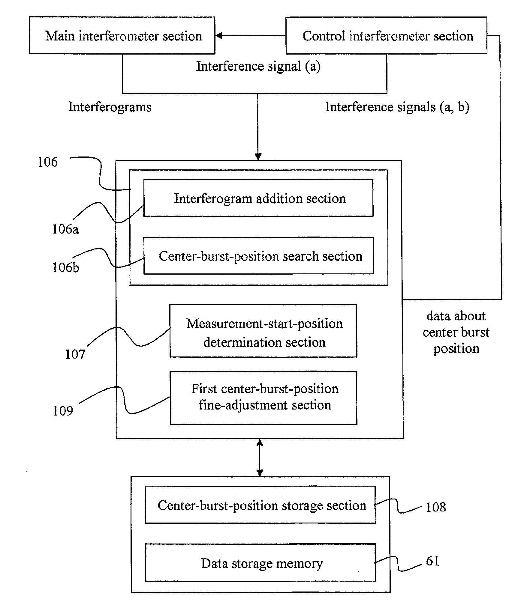
[0011]In view of the above circumstances, it is an object of the present invention to provide a Fourier transform infrared spectrophotometer capable of accurately detect a center burst position even when a sufficient light intensity does not reach a detector.
[0013]In the Fourier transform infrared spectrophotometer of the present invention, the center-burst-position detection section performs the addition processing of adding respective intensities of a designated number of interferograms, to produce a cumulative interferogram. In each of the interferograms, peaks around a center burst position (i.e., center and side bursts) appear in the approximately same pattern. Thus, intensities of the center and side bursts become larger as the number of interferograms subjected to the addition processing is increased. In contrast, noise peaks in each of the interferograms do not appear in the same pattern. Thus, even if the addition processing is performed, intensities of the noise peaks in the interferograms will be cancelled out and kept from being increased. In addition, a positional deviation between the center bursts in the interferograms can be calculated, because peaks around a center burst position appear in the approximately same pattern, as described above. That is, in a process of producing the cumulative interferogram, the addition processing can be performed while correcting a positional deviation of the center burst in each of the interferograms. This makes it possible to accurately detect a center burst position where the cumulative interferogram has a maximum intensity value. Thus, even if a light transmittance becomes low due to a high sample concentration, or light intensity to be reflected toward a detector becomes low due to an increase in light scattering during reflection measurement, a center burst position can be accurately detected without occurrence of undesirable situations where a center burst position is buried by noises, or a noise peak is erroneously recognized as a center burst.
[0026]For example, in this Fourier transform infrared spectrophotometer according to a specific embodiment of the present invention, when a maximum intensity value in an interferogram obtained through the fine-adjustment operation is less than the intensity threshold stored in the center-burst-position storage section, it is determined that a center burst position cannot be normally detected through the fine-adjustment operation, and a result of the fine-adjustment operation can be invalidated. In this case, the sample measurement operation will be performed based on the center burst position stored in the center-burst-position storage section. This makes it possible to prevent the sample measurement operation from being performed in an abnormal moving range of the movable mirror.

Problems solved by technology

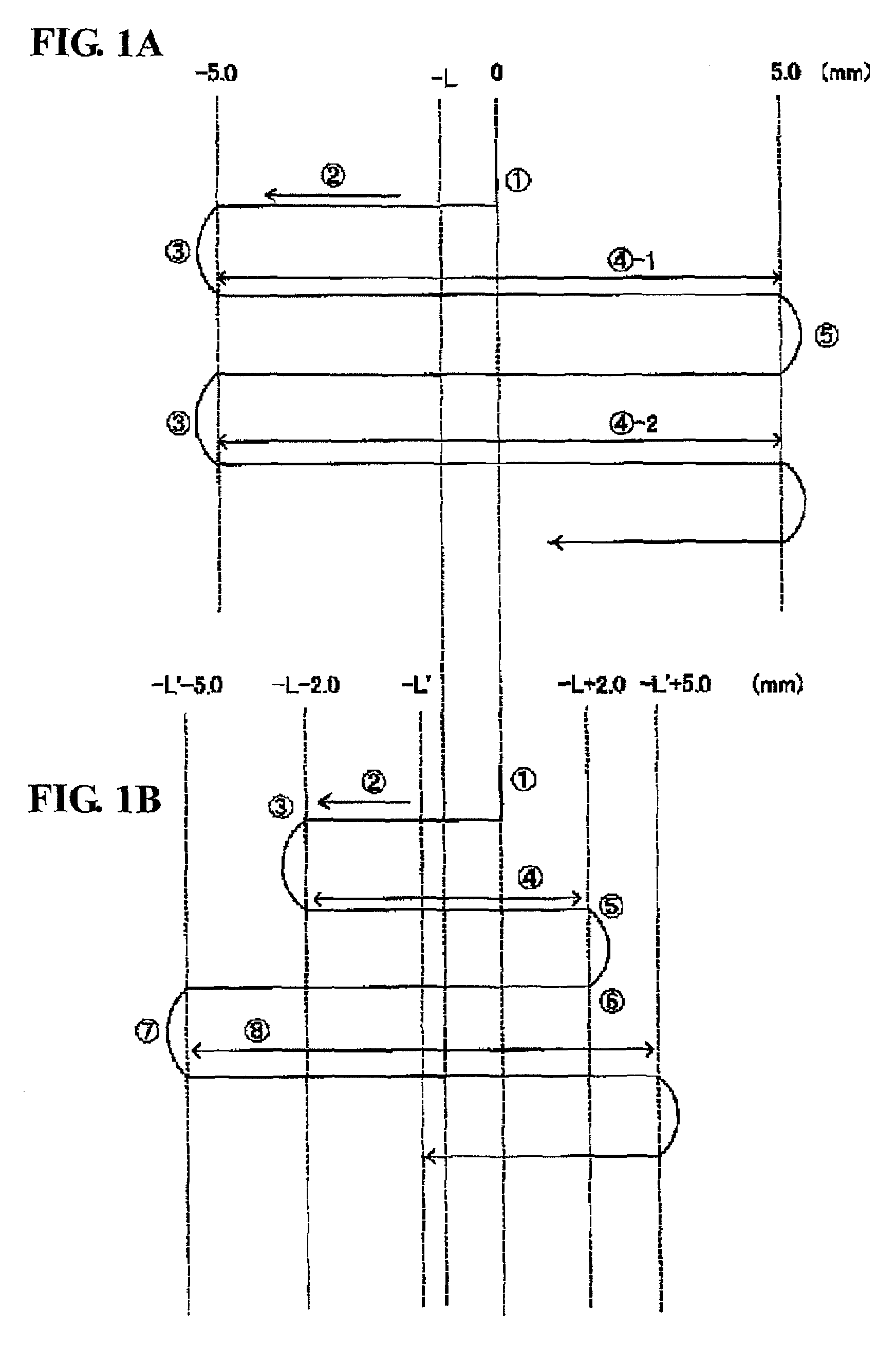
However, if a surface of a support base mounting the FTIR thereon largely inclines relative to a proper position, the center burst position (−L) will be largely deviated from a position in the interferogram corresponding to the gravitationally balanced position (1) to cause difficulty in accurately detect the center burst position (−L).
Although the moving range of the movable mirror 4 may be pre-set at a larger value to avoid the above situation, this approach involves a problem about an increase in time for the adjustment operation of moving the movable mirror 4 to detect a center burst position (−L), particularly, when considering that the adjustment operation has to be performed every time a sample is changed.
In reality, during an operation of detecting a center burst position (−L), a light intensity reaching a detector is likely to become insufficient, depending on a measurement technique (e.g., reflection measurement) or a type of sample.
This means that a center burst position (−L) is liable to be buried by noises, or a noise peak is liable to be erroneously recognized as a center burst.

Method used


Image

  • Fourier transform infrared spectrophotometer
  • Fourier transform infrared spectrophotometer
  • Fourier transform infrared spectrophotometer

Examples


Embodiment Construction

[0038]With reference to the drawings, an embodiment of the present invention will now be described.

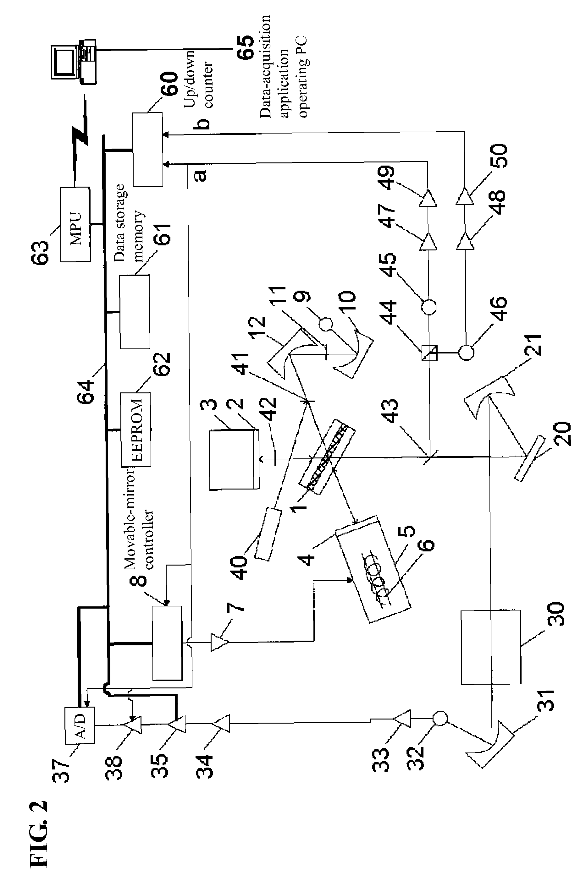
[0039]FIG. 2 is a schematic diagram generally showing a Fourier transform infrared spectrophotometer (FTIR) according to one embodiment of the present invention. As shown in FIG. 2, a beam splitter 1 is disposed to have an inclination of 30 degrees relative to a direction of a normal line of a fixed mirror 2 and a direction of a normal line of a movable mirror 4. The fixed mirror 2 is mounted to a fixed-mirror support block 3. The movable mirror 4 is supported by a sliding mechanism 5, in such a manner as to be moved close to and away from the beam splitter 1 along the direction of the normal line thereof according to a linear motor 6 of the sliding mechanism 5. A power amplifier 7 is provided as a means to apply a certain current to the linear motor 6, and a movable-mirror controller 8 is provided as a means to control a voltage to be applied to the linear motor 6 through the power am...


PUM

PropertyMeasurementUnit
wavenumberaaaaaaaaaa
wavenumber resolutionaaaaaaaaaa

Abstract

Disclosed is a Fourier transform infrared spectrophotometer, which comprises: a main interferometer section including a beam splitter, a fixed mirror, a movable mirror, and a phase plate disposed between the beam splitter and the fixed mirror; a control interferometer section having a quadrature control system for calculating a position of the movable mirror; a center-burst-position detection section operable, based on an input of interference signals and interferograms, to subject respective intensities of the interferograms to an addition processing while correcting a positional deviation of the movable mirror, so as to obtain a cumulative interferogram, and detecting a center burst position having a maximum intensity value in the cumulative interferogram; a center-burst-position storage section operable to store the detected center burst position; and a measurement-start-position determination section operable, based on the stored center burst position, to determine a measurement start position of the movable mirror during the measurement operation.

Description

BACKGROUND OF THE INVENTION[0001]1. Field of the Invention[0002]The present invention relates to a Fourier transform infrared spectrophotometer (FTIR) designed to control a movable mirror by means of a quadrature control. The FTIR is usable for qualitative and quantitative analyses of a sample and adaptable to a wide range of substances including polymeric and semiconducting materials, irrespective of whether they are organic or inorganic.[0003]2. Description of the Related Art[0004]Generally, a Fourier transform infrared spectrophotometer (FTIR) comprises a main interferometer section for performing a sample measurement operation, and a control interferometer section for instructing the main interferometer section to start data acquisition, and stabilizing a sliding speed of a movable mirror in the main interferometer section. In the control interferometer section, a control system called “quadrature control” is employed to calculate a position of the movable mirror. Specifically, ...

Claims


Application Information

Patent Timeline
Patent Type & Authority Patents(United States)
IPC IPC(8): G01B9/02G01J3/45G01J3/453G01N21/00G01N21/27G01N21/35G01N21/3563
CPCG01J3/02G01J3/027G01J3/45
Inventor YAMAMOTO, YOSHITAKE
Owner SHIMADZU CORP
Learn More