Pixel circuit, display and driving method thereof

a technology of pixel circuit and driving method, which is applied in the field of pixel circuit, can solve the problems of spoiling the uniformity of the screen, and the difficulty of fabricating large-size and high-definition displays, so as to reduce the influence of the carrier mobility, and reduce the influence of the threshold voltage

Active Publication Date: 2009-05-19
SONY CORP
View PDF7 Cites 37 Cited by
  • Summary
  • Abstract
  • Description
  • Claims
  • Application Information

AI Technical Summary

Benefits of technology

[0010]In consideration of such a problem of the related art, the present invention intends to provide a pixel circuit, a display, and a driving method thereof that each allows simultaneous correction of influence of both the threshold voltage and mobility, to thereby permit compensation of variation in the drain current (output current) supplied from the drive transistor. To this end, the following configuration is implemented. Specifically, according to an embodiment of the invention, there is provided a pixel circuit disposed at an intersection between a row scan line that supplies a control pulse and a column signal line that supplies a video signal. The pixel circuit includes a sampling transistor conducting in response to the control pulse supplied from the scan line to sample the video signal supplied from the signal line during a certain sampling period, a capacitance part holding an input potential dependent upon the sampled video signal, and a drive transistor supplying an output current during a certain emission period according to the input potential held by the capacitance part. The output current has dependence on a carrier mobility in a channel region of the drive transistor and dependence on a threshold voltage of the drive transistor. The pixel circuit also includes a light-emitting element caused, by the output current supplied from the drive transistor, to emit light with a luminance in response to the video signal, and correction means correcting both the dependence of the output current on the carrier mobility and the dependence of the output current on the threshold voltage simultaneously. The correction section is connected to the drive transistor and the capacitance part, and operates during a correction period preceding to the sampling period. The correction period is separated into a reset period and a detection period. During the reset period, the correction section energizes the capacitance part to reset the potential held by the capacitance part. During the detection period, the correction section stops the energization and detects a potential difference arising between a source and a gate of the drive transistor during a period when a transient current flows through the drive transistor. The capacitance part holds a potential corresponding to the detected potential difference. The held potential includes both a potential component for reducing influence of the threshold voltage on the output current of the drive transistor, and a potential component for reducing influence of the carrier mobility on the output current of the drive transistor.
[0011]Furthermore, according to an embodiment of the invention, there is provided a display that includes a pixel array part having scan lines disposed on rows, signal lines disposed on columns, and a matrix of pixels disposed at intersections between the scan and signal lines, a signal part supplying a video signal to the signal lines, and a scanner part supplying a control pulse to the scan lines to sequentially scan the pixels for each row. Each of the pixels includes at least a sampling transistor, a capacitance part, a drive transistor, and a light-emitting element. The sampling transistor conducts in response to a sampling control pulse supplied from the scan line to sample the video signal supplied from the signal line during a certain sampling period. The capacitance part holds an input potential dependent upon the sampled video signal. The drive transistor supplies an output current during a certain emission period according to the input potential held by the capacitance part. The output current has dependence on a carrier mobility in a channel region of the drive transistor and dependence on a threshold voltage of the drive transistor. The light-emitting element is caused, by the output current supplied from the drive transistor, to emit light with a luminance in response to the video signal. Each of the pixels includes correction means that corrects both the dependence of the output current on the carrier mobility and the dependence of the output current on the threshold voltage simultaneously. The correction section is connected to the drive transistor and the capacitance part, and operates during a correction period preceding to the sampling period. The correction period is separated into a reset period and a detection period. During the reset period, the correction section energizes the capacitance part to reset the potential held by the capacitance part. During the detection period, the correction section stops the energization and detects a potential difference arising between a source and a gate of the drive transistor during a period when a transient current flows through the drive transistor. The capacitance part holds a potential corresponding to the detected potential difference. The held potential includes both a potential component for reducing influence of the threshold voltage on the output current of the drive transistor, and a potential component for reducing influence of the carrier mobility on the output current of the drive transistor. The scanner part includes at least a write scanner, a drive scanner, and a correction scanner. The write scanner supplies the sampling control pulse to the scan lines during the sampling period. The correction scanner supplies a correction control pulse that defines the correction period to the scan lines. The drive scanner supplies a drive control pulse to the scan lines. The drive control pulse differentiates the reset period from the detection period in the correction period and differentiates an emission period from a non-emission period other than the emission period.
[0012]Moreover, according to an embodiment of the invention, there is provided a method of driving a pixel circuit disposed at an intersection between a row scan line that supplies a control pulse and a column signal line that supplies a video signal. The pixel circuit includes at least a sampling transistor, a capacitance part, a drive transistor and a light-emitting element. The sampling transistor conducts in response to the control pulse supplied from the scan line to sample the video signal supplied from the signal line during a certain sampling period. The capacitance part holds an input potential dependent upon the sampled video signal. The drive transistor supplies an output current during a certain emission period according to the input potential held by the capacitance part. The output current has dependence on a carrier mobility in a channel region of the drive transistor and dependence on a threshold voltage of the drive transistor. The light-emitting element is caused, by the output current supplied from the drive transistor, to emit light with a luminance in response to the video signal. The method includes a correction step for correcting both the dependence of the output current on the carrier mobility and the dependence of the output current on the threshold voltage simultaneously during a correction period preceding to the sampling period. The correction period is separated into a reset period and a detection period. The correction step includes the sub steps of: energizing the capacitance part to reset the potential held by the capacitance part during the reset period; and stopping the energization and detecting a potential difference arising between a source and a gate of the drive transistor during a period when a transient current flows through the drive transistor during the detection period. The method also includes a holding step for holding a potential corresponding to the detected potential difference in the capacitance part. The held potential includes both a potential component for reducing influence of the threshold voltage on the output current of the drive transistor, and a potential component for reducing influence of the carrier mobility on the output current of the drive transistor.
[0013]In addition, according to an embodiment of the invention, there is provided a method of driving a display including a pixel array part, a scanner part and a signal part. The pixel array part includes scan lines disposed on rows, signal lines disposed on columns, and a matrix of pixels disposed at intersections between the scan and signal lines. The signal part supplies a video signal to the signal lines. The scanner part supplies a control pulse to the scan lines to sequentially scan the pixels for each row. Each of the pixels includes at least a sampling transistor, a capacitance part, a drive transistor and a light-emitting element. The sampling transistor conducts in response to a sampling control pulse supplied from the scan line to sample the video signal supplied from the signal line during a certain sampling period. The capacitance part holds an input potential dependent upon the sampled video signal. The drive transistor supplies an output current during a certain emission period according to the input potential held by the capacitance part. The output current has dependence on a carrier mobility in a channel region of the drive transistor and dependence on a threshold voltage of the drive transistor. The light-emitting element is caused, by the output current supplied from the drive transistor, to emit light with a luminance in response to the video signal. The method includes a correction step for correcting at each pixel both the dependence of the output current on the carrier mobility and the dependence of the output current on the threshold voltage simultaneously during a correction period preceding to the sampling period. The correction period is separated into a reset period and a detection period. The correction step includes the sub steps of: energizing the capacitance part to reset the potential held by the capacitance part during the reset period; and stopping the energization and detecting a potential difference arising between a source and a gate of the drive transistor during a period when a transient current flows through the drive transistor during the detection period. The method also includes a holding step for holding a potential corresponding to the detected potential difference in the capacitance part. The held potential includes both a potential component for reducing influence of the threshold voltage on the output current of the drive transistor, and a potential component for reducing influence of the carrier mobility on the output current of the drive transistor. The method further includes a write scanning step for supplying the sampling control pulse to the scan lines during the sampling period, a correction scanning step for supplying a correction control pulse that defines the correction period to the scan lines, and a drive scanning step for supplying a drive control pulse to the scan lines. The drive control pulse differentiates the reset period from the detection period in the correction period and differentiates an emission period from a non-emission period other than the emission period.
[0014]According to an embodiment of the invention, the pixel circuit corrects both the dependence of the output current on the carrier mobility and that on the threshold voltage simultaneously. Specifically, in a certain detection period, the potential difference arising between the source and gate of the drive transistor is detected during the period when a transient current for detection flows through the drive transistor, and the detected potential difference is fed back to the capacitance part. Since the detection period is set shorter than conventional one, the potential difference between the source and gate can be detected while the transient current is flowing. As a result, the potential corresponding to the detected potential difference includes a potential component for reducing the influence of the carrier mobility on the output current of the drive transistor as well as a potential component for reducing the influence of the threshold voltage thereon. If the detection period is long and therefore the potential difference between the source and gate is detected after the transient current has disappeared as is conventional, the resulting potential includes only a potential component for reducing the influence of the threshold voltage. Detecting the potential difference in the current-flowing state allows acquisition of information relating to the carrier mobility. Since the influence of the threshold voltage and mobility can be eliminated for each pixel, variation in the output current among pixels can be suppressed over the entire pixel array. In particular, the dependence of the output current on the mobility is high when displaying a gray-scale in a range of gray to white. According to an embodiment of the invention, variation in the output current due to the mobility variation can be suppressed, and thus the uniformity of the screen can be significantly improved when displaying a gray-scale in a range of gray to white. According to an embodiment of the invention, adequate timing control is implemented with maintaining the conventional pixel circuit configuration basically, to thereby allow correction of both threshold voltage variation and mobility variation. Therefore, variation in the output current can be suppressed without increasing the number of elements in the pixel circuit.
[0015]In addition, According to an embodiment of the invention, the potential held by the capacitance part is reset during the reset period preceding to the detection period in order to stably detect the transient current flowing through the drive transistor. This reset operation flows a through-current in the drive transistor although instantaneous, which causes anomalous light-emission of the light-emitting element. This anomalous emission is unnoticeable when displaying a gray-scale in a range of gray to white. However, when displaying black, this anomalous emission problematically causes so-called “floating black”, spoiling the contrast on the screen. The embodiments of the invention minimize the time length of the reset period for suppressing the through-current, to thereby prevent “floating black”.

Problems solved by technology

The simple-matrix method employs a simple structure, but involves difficulties of fabricating large-size and high-definition displays.
Thus, the luminance varies depending on each pixel, which spoils the uniformity of the screen.
As a result, the emission luminance varies from pixel to pixel, problematically spoiling the uniformity of a screen.

Method used


Image

  • Pixel circuit, display and driving method thereof
  • Pixel circuit, display and driving method thereof
  • Pixel circuit, display and driving method thereof

Examples


Embodiment Construction

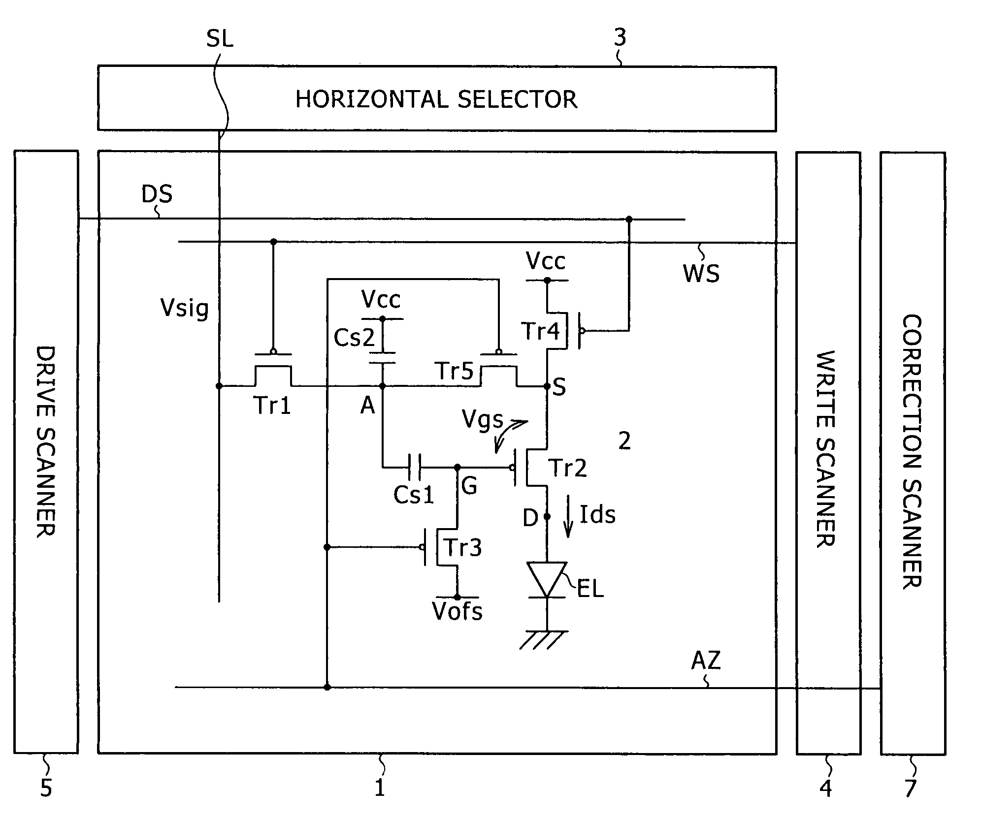
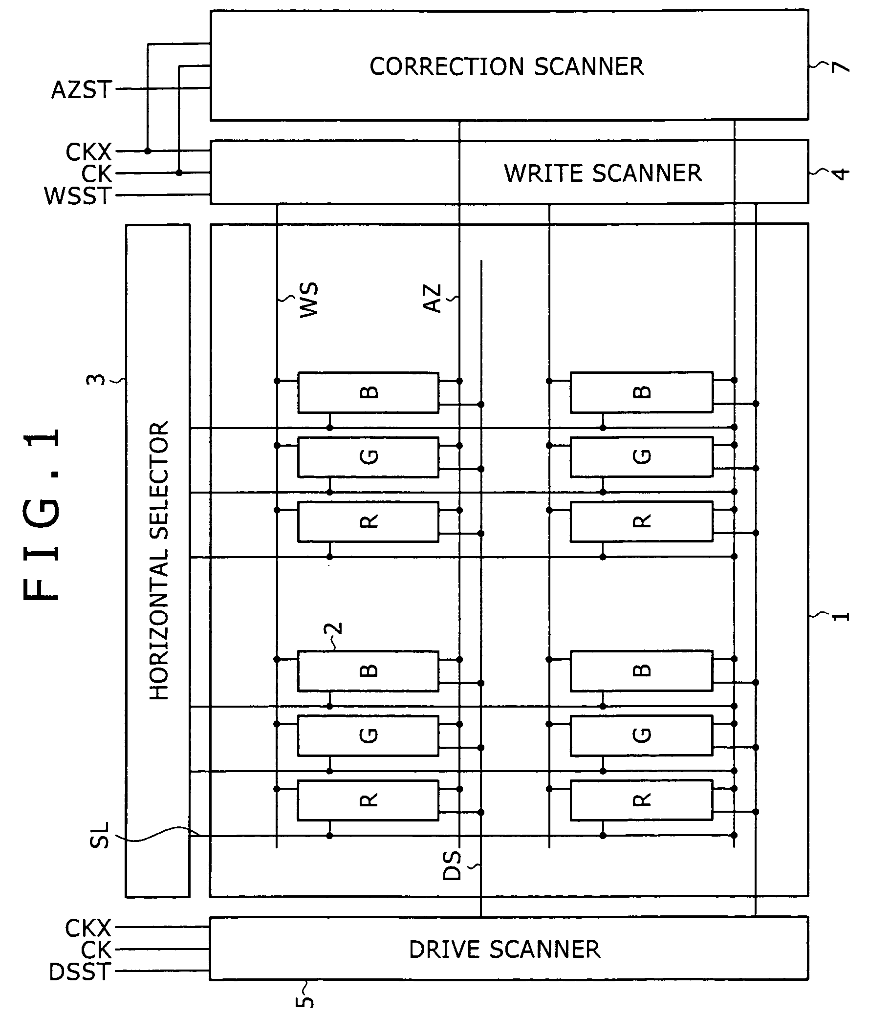
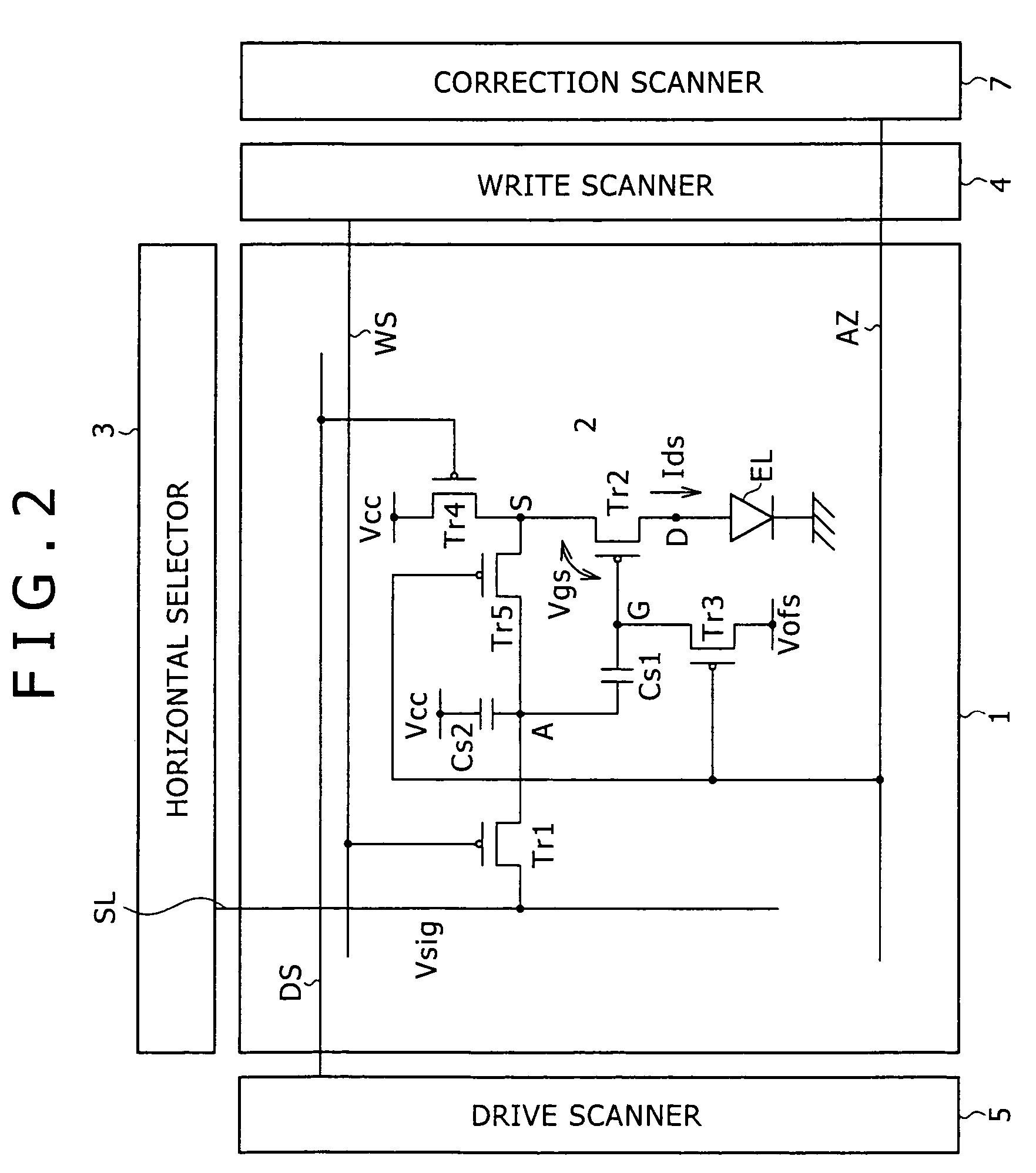
[0029]Embodiments of the present invention will be described in detail below with reference to the accompanying drawings. Initially, in order to clearly show the concept of the invention, the basic configuration of an active-matrix display will be described with reference to FIG. 1. Referring to FIG. 1, the active-matrix display is composed of a pixel array 1, which is an essential part, and peripheral circuit parts. The peripheral circuit parts include a horizontal selector 3, a write scanner 4, a drive scanner 5, a correction scanner 7, and so on. The pixel array 1 is composed of row scan lines WS, column signal lines SL, and pixels R, G and B that are disposed in a matrix at intersections between the scan and signal lines. Although this display includes pixels of three primary colors of RGB to allow color displaying, the present invention is not limited thereto. Each of the pixels R, G and B is composed of a pixel circuit 2. The signal lines SL are driven by the horizontal select...


PUM


Abstract

The invention provides a pixel circuit that allows simultaneous correction of both influence of the threshold voltage of a drive transistor and influence of the mobility of the drive transistor. Correction means is connected to a drive transistor and a capacitance part, and operates during a correction period preceding to a sampling period. The correction period is separated into a reset period and a detection period. During the reset period, the correction means energizes the capacitance part to reset the potential of the capacitance part. During the detection period, the correction means stops the energization and detects the potential difference arising between the source and gate of the drive transistor during the period when a transient current flows through the drive transistor. The capacitance part holds the potential corresponding to the detected potential difference. The held potential includes both a potential component for reducing the influence of the threshold voltage on the output current of the drive transistor, and a potential component for reducing the influence of the carrier mobility thereon.

Description

BACKGROUND OF THE INVENTION[0001]The present invention relates to a pixel circuit for current-driving a light-emitting element provided for each pixel. The invention also relates to a display that includes the pixel circuits arranged in a matrix, and particularly to an active-matrix display that controls the amount of a current applied to a light-emitting element, such as an organic electro-luminescence (EL) element, by use of insulated-gate field effect transistors provided in the respective pixel circuits.[0002]In an image display, e.g., a liquid crystal display, plural liquid crystal pixels are arranged in a matrix, and the transmitted intensity or reflected intensity of incident light is controlled for each pixel based on information of images to be displayed, to thereby display the images. The similar principle also holds for an organic EL display employing organic EL elements for its pixels. The organic EL element is a self-emitting element unlike the liquid crystal element. T...

Claims


Application Information

Patent Timeline
Patent Type & Authority Patents(United States)
IPC IPC(8): G09G3/30H05B44/00
CPCG09G3/3233G09G3/3266G09G3/3291G09G2300/043G09G2300/0819G09G2300/0852G09G2300/0861G09G2320/043
Inventor YAMASHITA, JUNICHIUCHINO, KATSUHIDEYAMAMOTO, TETSUROTOYOMURA, NAOBUMI
Owner SONY CORP
Why Eureka
Try Eureka