Compression assembly of spatial heterodyne spectrometer (SHS)

a heterodyne spectrometer and compression assembly technology, applied in the field of compression assembly of spatial heterodyne spectrometers, can solve the problems of complicated adjustment of optics mounts, particularly sensitive to vibration, and the general weight of conventional discrete optical element types of shs interferometers

Inactive Publication Date: 2009-05-19
THE UNITED STATES OF AMERICA AS REPRESENTED BY THE SECRETARY OF THE NAVY
View PDF0 Cites 20 Cited by
  • Summary
  • Abstract
  • Description
  • Claims
  • Application Information

AI Technical Summary

Benefits of technology

[0019]The present invention provides a technique that simplifies the production, assembly, and alignment of SHS interferometers, while preserving the robustness achieved by monolithic SHS interferometers.
[0020]The present invention provides a way to fabricate rugged SHS interferometers in a faster, more flexible, and much more cost effective way by avoiding optical contacts. Avoiding optical contacts significantly relaxes the surface flatness requirements. The mechanical tolerances are then driven by the optical performance only, which yields especially relaxed tolerances for longer wavelengths, e.g. in the infrared. It also provides the option of using different spacer materials in the interferometer, which allows more flexibility in the temperature compensation of the interferometer if it is needed.
[0022]The invention combines the ruggedness, self-alignment, and a lightweight of the monolithic design with the flexibility and cost effectiveness of the discrete components design. Accordingly, the main obstacles of the conventional systems can be overcome, which have previously impeded the application of SHS for widespread commercial or military applications, namely the vibration sensitivity and unit cost.
[0023]Advantages of the compression assembly of the present invention over discrete components include the compression assembly being more robust and being self-aligned. The specific advantages of the compression assembly of the present invention over an optically contacted, monolithic interferometer include: the surface flatness requirements being relaxed because they arc not driven by the optical contacting (i.e., there is a significant cost advantage); the compression assembly being easily disassembled and components therein being easily replaced; and there being no need to manufacture the spacers from the same material as the optical components.

Problems solved by technology

In order to build a rugged interferometer, the holding fixtures have to be very stiff and the adjustable optics mounts get complicated.
This set up is particularly sensitive to vibration since the commercial mounts are not optimized for stiffness.
In any event such conventional discrete optical element types of SHS interferometers generally are relatively heavy as a result of the required mounting systems and have very time consuming adjustment procedures.
The conventional discrete optical elements design of SHS is appropriate for laboratory investigations but the inherent lack of ruggedness excludes these designs from virtually all operational applications that are based on platforms like land vehicles, airplanes, unmanned aerial vehicles (UAVs), satellites, or even a handheld device which has to withstand rough environments to be reliable.
Moreover, the realignment of a misaligned interferometer is not trivial and requires a trained person and appropriate equipment, thus further hampering the use of this assembly technique for commercial or military devices.
Unfortunately, as a consequence of the strong bond between the surfaces, a monolithic interferometer cannot easily be disassembled without risking the destruction of the entire interferometer.
However, polishing the interface surfaces to meet the precision and accuracy required for the optical contacting is very labor intensive, since it has to be performed partly by hand.
Therefore, this production technique is very expensive and time consuming (over one hundred thousand USD per interferometer).
A monolithic interferometer is appropriate e.g. for one of a kind satellite instruments, but again, it is not suitable for wide spread applications in the commercial or military sector due to its high cost.
In summary, the conventional design and assembly techniques for SHS interferometers seriously impede the development of SHS spectrometers for wide spread applications in the commercial or military sector.
The main reasons are either the sensitivity to vibration or the prohibitive cost per unit.

Method used


Image

  • Compression assembly of spatial heterodyne spectrometer (SHS)
  • Compression assembly of spatial heterodyne spectrometer (SHS)
  • Compression assembly of spatial heterodyne spectrometer (SHS)

Examples


Embodiment Construction

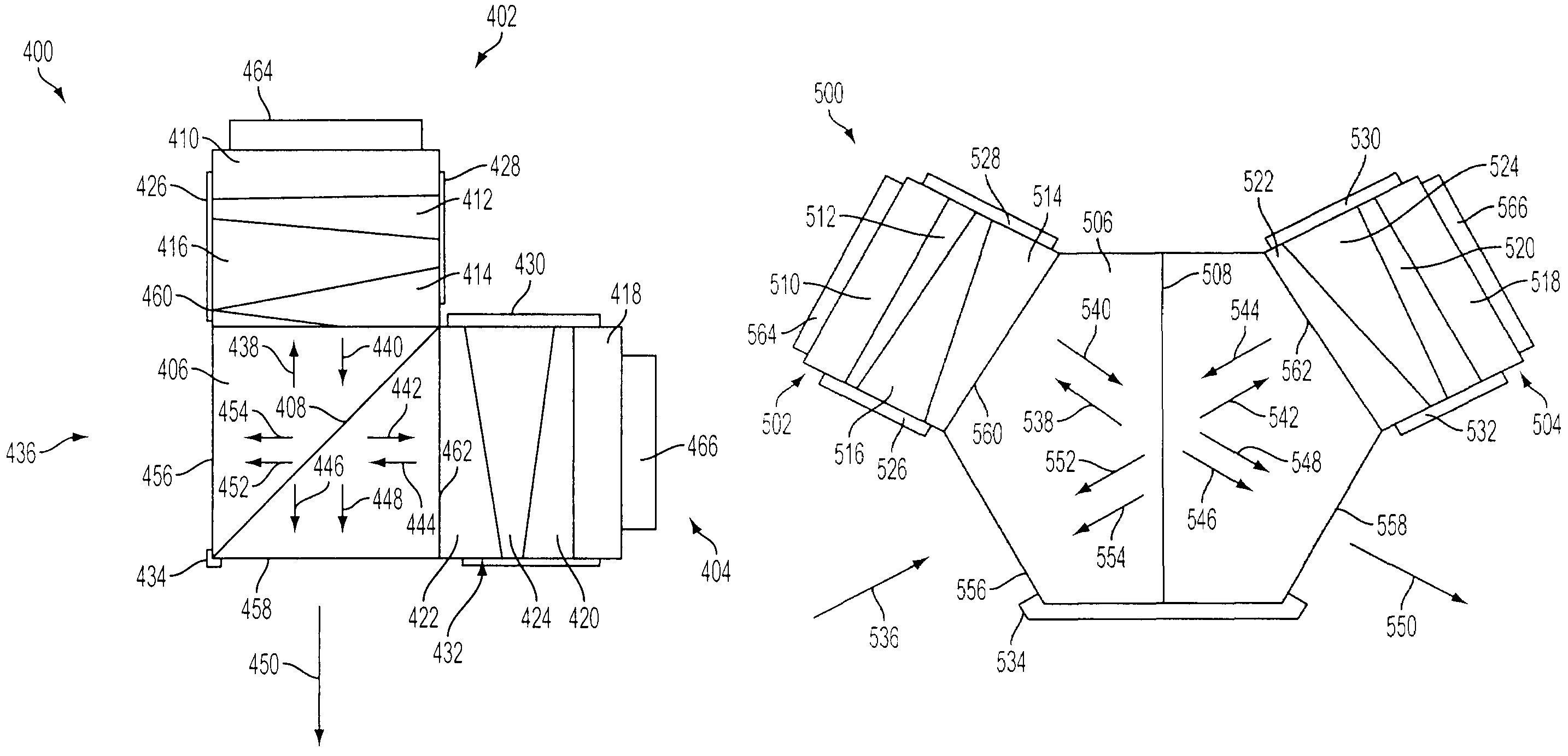
[0031]FIG. 4 illustrates a cubic interferometer SHS compression assembly for use in a SHS interferometer in accordance with an exemplary embodiment of the invention. As seen in the figure interferometer 400 includes an optical beamsplitter 406, a first leg portion 402, a second leg portion 404, a First retaining portion 464, and a second retaining portion 466. Optical beamsplitter 406 includes an input face 456, an output face 458, a first processing face 460, and a second processing face 462. First leg portion 402 includes a first optical grating 410, a first field-widening prism 416 and a first spacer system. Second leg portion 404 includes a second optical grating 418, a second field-widening prism 424 and a second spacer system. First retaining portion 464 keeps first leg portion 402 in contact with optical beamsplitter 406 at first processing face 460. Second retaining portion 466 keeps the second leg portion 404 in contact with optical beamsplitter 406 at second processing fac...


PUM


Abstract

The present invention provides an economically feasible robust spatial heterodyne spectroscopy (SHS) interferometer. A first type prior art monolithic SHS interferometer is exceedingly expensive, whereas a second type of prior art SHS interferometer is extremely large and has many components, which need to be tuned. The present invention is much less expensive than the first type of prior art SHS interferometer and is much smaller that the second type of prior art SHS interferometer.

Description

[0001]This Application claims the benefit of U.S. Provisional Application No. 60 / 740,295, filed Nov. 18, 2005, the entire disclosure of which is incorporated herein by reference.BACKGROUND[0002]Spatial heterodyne spectroscopy (SHS) was conceived in the late 1980s by Prof. Fred Roesler and his graduate student John Harlander at the University of Wisconsin. SHS interferometers include a beamsplitter two gratings, and two (optional) field-widening prisms. A detailed description of SHS can be found in “Robust monolithic ultraviolet interferometer for the SHIMMER instrument on STPSat-1”, APPLIED OPTICS, vol. 42, Nol. 15, 20 May 2003, by J. M. Harlander et al. The optical components of SHS interferometers have to be mounted within tight. interferometeric tolerances to achieve high performance. There are generally two types of conventional SHS interferometer configurations, those with discrete optical elements and those with a monolithic optical element.[0003]FIG. 1 illustrates an exemplar...

Claims


Application Information

Patent Timeline
Patent Type & Authority Patents(United States)
IPC IPC(8): G01J3/45G01B9/02
CPCG01J3/12G01J3/4531G01J3/4532G01J3/0259
Inventor ENGLERT, CHRISTOPH R
Owner THE UNITED STATES OF AMERICA AS REPRESENTED BY THE SECRETARY OF THE NAVY
Why Eureka
Try Eureka