Flow control valve

a flow control and valve seat technology, applied in the direction of diaphragm valves, valve housings, engine diaphragms, etc., can solve the problems of gradual deformation or creep of the valve seat, and achieve the effect of improving flow stability, reducing the size of the facility, and improving flow stability

Inactive Publication Date: 2009-05-26
CKD
View PDF35 Cites 39 Cited by
  • Summary
  • Abstract
  • Description
  • Claims
  • Application Information

AI Technical Summary

Benefits of technology

[0035]The present invention has been made in view of the above circumstances and has an object to provide a compact flow control valve with high flow stability.
[0036]To achieve the purpose of the invention, there is provided a flow control valve for controlling a flow rate, comprising: a valve body made of resin including; a first passage formed in the valve body; a valve port communicating with the first passage; and a valve seat formed around the valve port; a valve element movable into contact with and away from the valve seat; a valve chamber formed around the valve seat; a second passage communicating with the valve chamber; and a flow adjustment rod for adjusting a flow rate of a fluid allowed to flow in the valve chamber, wherein the flow adjustment rod is adjustable in position to change an opening degree of the valve element relative to the valve seat for adjusting the flow rate, and the flow control valve further comprises an annular recess formed in an inner periphery of the valve seat formed surrounding the valve port and configured to prevent radial deformation of the valve port when the valve element is moved into contact with the valve seat.
[0041]On the other hand, according to the present invention, an annular recess is formed in the valve seat in such a manner-that part of the valve seat is cut away to provide a space for the annular recess. This annular recess serves to prevent the stress applied to the valve seat from propagating to the inner surface of the valve port. This is shown in the simulation result shown in FIG. 5. Specifically, with the annular recess provided in the valve seat, the direction of stress propagation can be changed to increase a propagation distance, thereby preventing creep deformation of the valve port in the diameter decreasing direction.
[0042]Further, the stress applied to the valve seat may also cause deformation of the valve port radially outward, i.e., in a diameter increasing direction. In particular, if the diameter of an opening edge of the valve port is increased, the flow rate will change disadvantageously. According to the present invention, however, it is also possible to prevent such creep deformation.
[0044]According to the present invention, therefore, the flow control valve can avoid any influence of stress that may cause deformation of the valve port in the radial direction, resulting in improved flow stability. Furthermore, it is unnecessary to separately provide the flow control section and the flow shut-off section and hence the valve body of the flow control valve can be reduced in size, contributing to downsizing of facilities.
[0045]In other words, the present invention can provide the compact flow control valve with high flow stability.

Problems solved by technology

Even in the flow control valve comprising the resin valve body, when the valve seat is subjected to repeated stress by the valve element in contacting the valve seat, the valve seat will gradually be deformed, or creep.

Method used


Image

  • Flow control valve
  • Flow control valve
  • Flow control valve

Examples


first embodiment

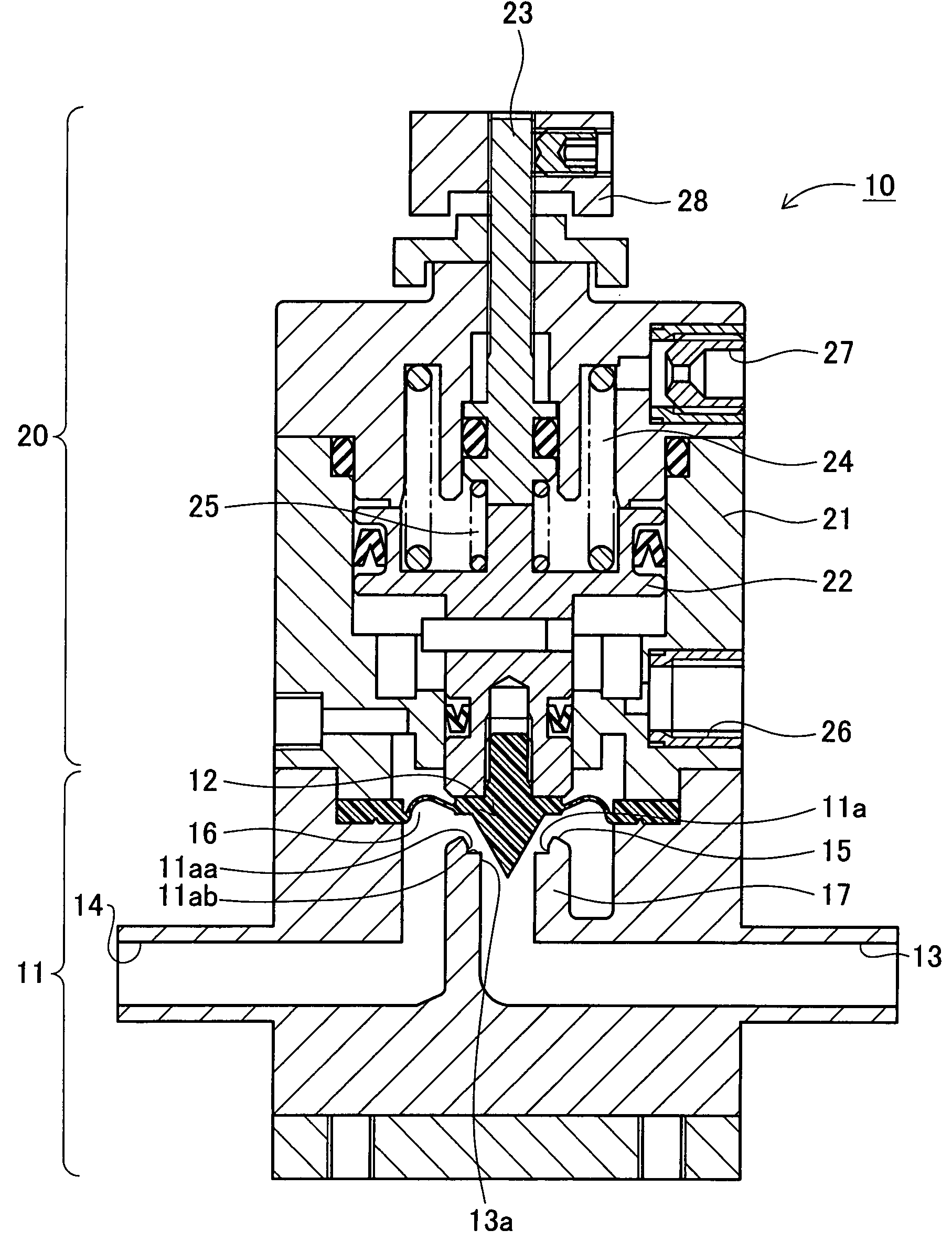
[0062]FIG. 1 is a sectional view of a flow control valve of the first embodiment, showing a valve open state. The flow control valve 10 comprises a body section 11 and an operation section 20. The body section 11 is made of resin such as PFA, which is highly resistant to chemicals. Please note that in the figures the resin body section 11 and a resin actuator body 21 mentioned later are indicated by single cross-hatching generally used for a metal section for easy viewing.

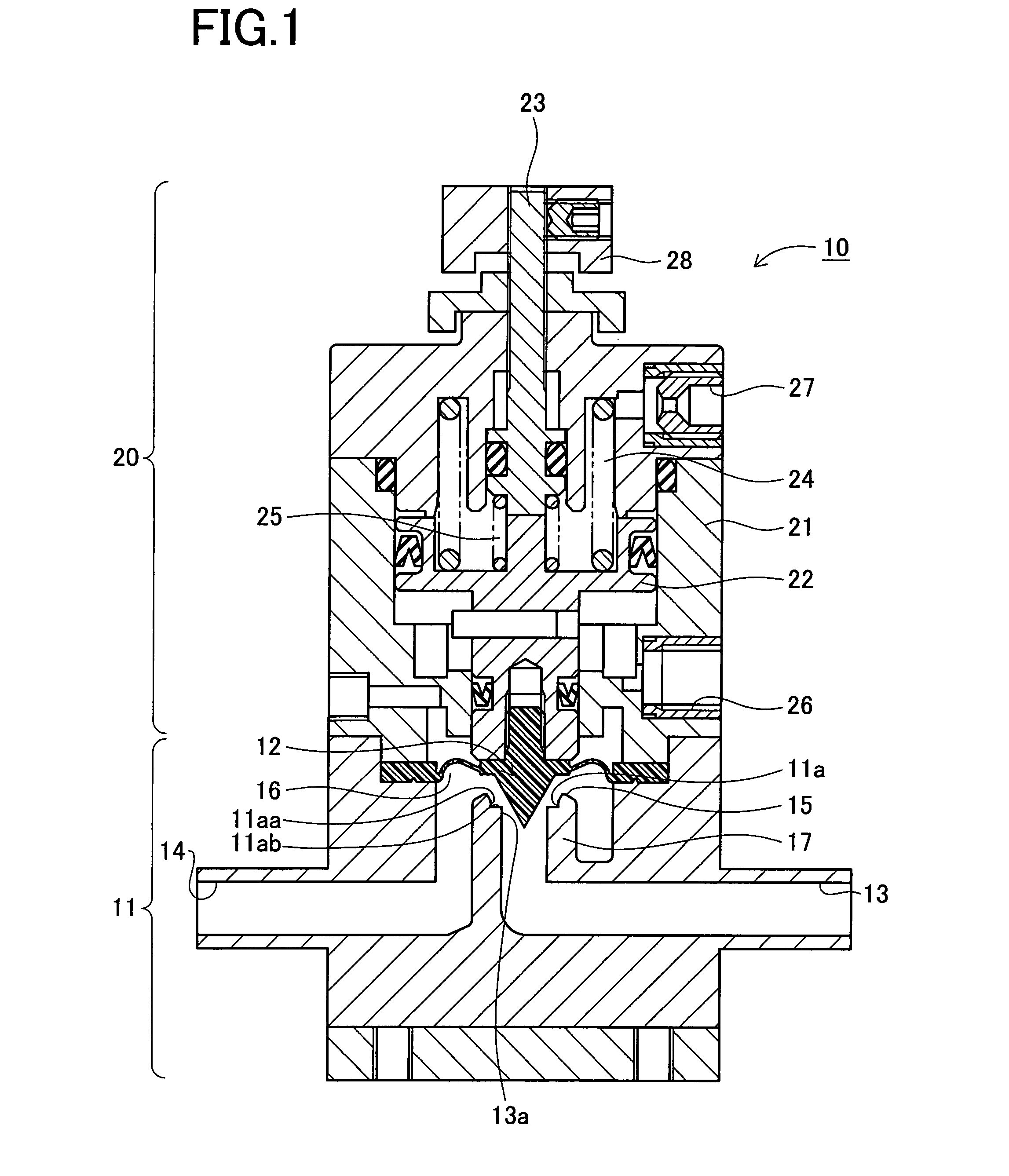
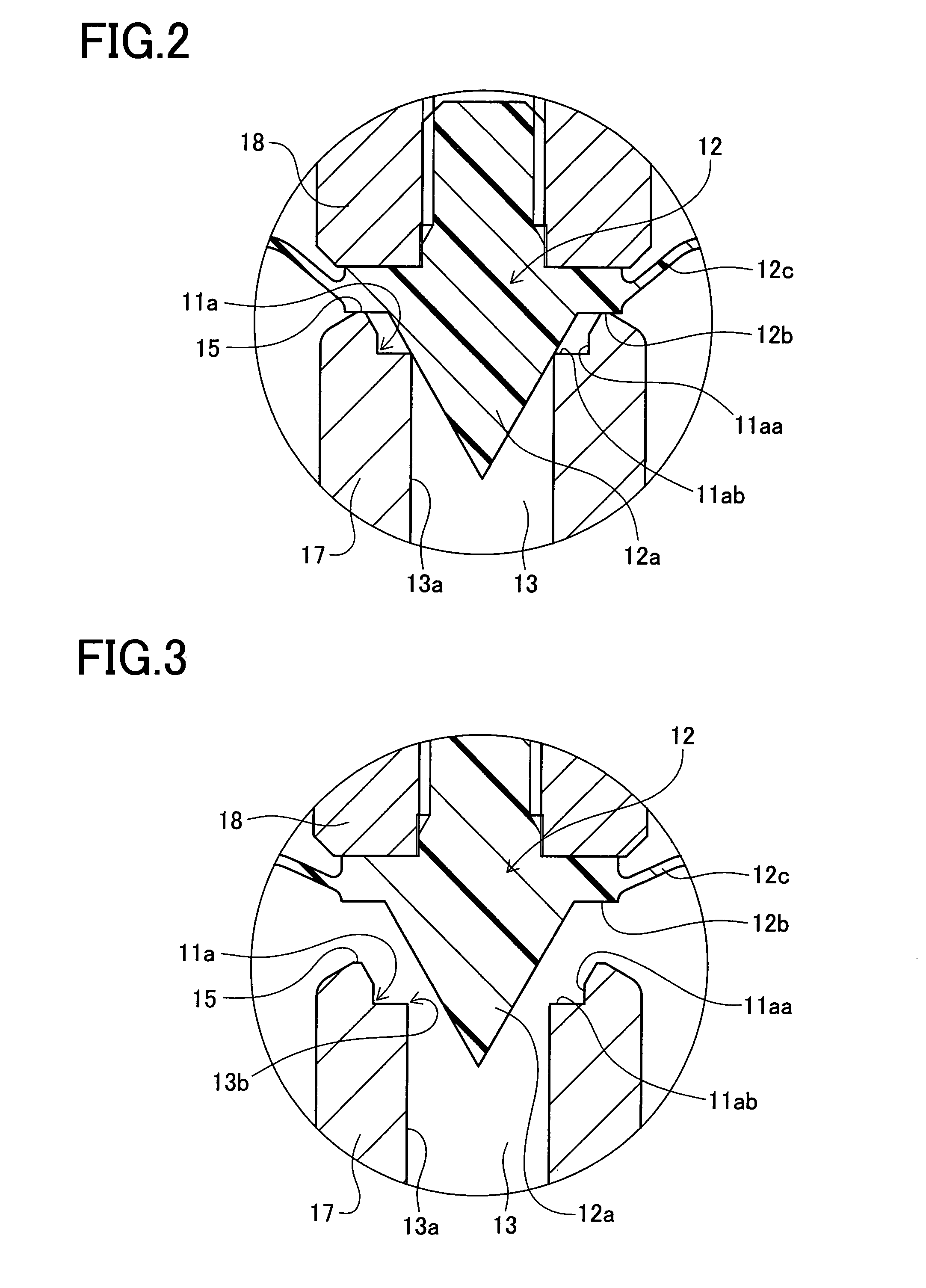
[0063]The body section 11 is provided with a first passage 13, a second passage 14, a valve seat 15, and a valve chamber 16. The first passage 13 is allowed to communicate with the valve chamber 16 through a valve port 13a and communicate with the second passage 14 communicating with the valve chamber 16 for permitting a chemical or another fluid to pass therethrough. The first passage 13 is formed in a cylindrical part 17, at the top of which the annular valve seat 15 is provided around the valve port 13a.

[0064]I...

second embodiment

[0128]A second embodiment of the present invention will be described below. The configuration of the second embodiment is substantially identical to that of the first embodiment. The following explanation is therefore made with a focus on a difference from the first embodiment.

[0129]The difference is the shape of an annular recess 11a, which is shown in FIGS. 7 and 8. FIG. 7 is an enlarged sectional view of a valve seat and its surrounding portion in a flow control valve of the second embodiment, showing a valve closed state. FIG. 8 is an enlarged sectional view of the valve seat and its surrounding portion in the flow control valve of the second embodiment, showing an opened state.

[0130]As shown in FIGS. 7 and 8, the annular recess 11a is of a sectional shape formed by cutting away a portion of the valve seat 15 at a slant, providing two different angled surfaces (an upper side surface 11aa and a lower side surface 11ab) joined at an obtuse angle, instead of the two surfaces (the v...

third embodiment

[0142]A third embodiment of the present invention will be described below.

[0143]The construction of the third embodiment is substantially identical to that of the first embodiment. The following explanation is therefore made with a focus on a difference from the first embodiment.

[0144]FIG. 9 is an enlarged sectional view of a valve seat and its surrounding portion in a flow control valve of the third embodiment, showing a valve closed state. FIG. 10 is an enlarged sectional view of the valve seat and its surrounding portion in the flow control valve of the third embodiment, showing a valve open state.

[0145]The difference is the shape of a needle 12a of a valve element 12. The needle 12a of the third embodiment is formed in a cylindrical shape having a lower tapered surface for controlling a flow rate.

[0146]Specifically, the needle 12a includes a cylindrical portion 12aa and a tapered portion 12ab. The cylindrical portion 12aa has a diameter smaller than the inner diameter of the val...


PUM


Abstract

A compact flow control valve with high flow stability is arranged to comprises: a valve body made of resin including; a first passage formed in the valve body; a valve port communicating with the first passage; and a valve seat formed around the valve port; a valve element movable into contact with and away from the valve seat; a valve chamber formed around the valve seat; a second passage communicating with the valve chamber; and a flow adjustment rod for adjusting a flow rate of a fluid allowed to flow in the valve chamber, wherein the flow adjustment rod is adjustable in position to change an opening degree of the valve element relative to the valve seat for adjusting the flow rate, and the flow control valve further comprises an annular recess formed in an inner periphery of the valve seat formed surrounding the valve port and configured to prevent radial deformation of the valve port when the valve element is moved into contact with the valve seat.

Description

BACKGROUND OF THE INVENTION[0001]1. Field of the Invention[0002]The present invention relates to a flow control valve for controlling the flow rate of a fluid and shutting off the flow of the fluid and, more particularly, to a flow control valve with improved flow control capability to a small amount-range.[0003]2. Description of Related Art[0004]In a semiconductor manufacturing process, chemicals are often used in small amounts. Therefore a technique of controlling such small amounts of chemicals has been demanded.[0005]The above demand for supply of small amounts of chemicals has been increased due to the following factors for example. One is that, for applying a chemical onto a wafer to form a film thereon, there has been developed a technique of putting a small amount of a chemical by drop on the wafer and expanding the dropped chemical by a centrifugal force or the like. Another is that chemicals to be used are specific and expensive, and hence wasteful consumption of such expe...

Claims


Application Information

Patent Timeline
Patent Type & Authority Patents(United States)
IPC IPC(8): F16K1/12
CPCF16K1/38F16K1/42F16K7/16F16K27/0236
Inventor NAGAI, KIYOSHI
Owner CKD
Why Eureka
Try Eureka