Optical probe and optical tomography system

a technology of optical tomography and optical probe, which is applied in the field of optical probes, can solve the problems of optical fiber damage, difficult to make thinner optical probes, and difficult to pass optical fibers through cylindrical shafts, etc., and achieves the effect of low cost and high wear resistan

Inactive Publication Date: 2009-05-26
FUJIFILM CORP
View PDF3 Cites 69 Cited by
  • Summary
  • Abstract
  • Description
  • Claims
  • Application Information

AI Technical Summary

Benefits of technology

[0012]In view of the foregoing observations and description, the primary object of the present invention is to provide an optical probe which is easy to make thin, can be produced at low cost and at the same time the light emitted from the outer peripheral surface of the outer probe of the optical probe is orderly deflected to generate an orbit in a plane.
[0013]Another object of the present invention is to provide an optical tomography system which can be miniaturized and can be manufactured at low cost by the use of such an optical probe.
[0014]In accordance with the present invention, the above objects are accomplished by avoiding a complicated structure of passing a hollow shaft through the outer envelope of the optical probe and passing an optical fiber through the shaft, employing a structure where the optical fiber is rotated in the probe outer envelope and then causing a bearing portion provided outside the probe outer envelope to bear the optical fiber for rotation.

Problems solved by technology

However, in the optical probe disclosed in Japanese Patent No. 3104984, it is necessary to have a certain wall thickness to ensure the strength of the shaft and to ensure a space between the shaft and the optical fiber inside thereof, which makes difficult to make thinner the optical probe.
However, to realize this, it is necessary to make a probe as long as several meters, and it is very difficult to pass an optical fiber through the inside of a shaft which is cylindrical and elongated.
Further, the optical fiber can be damaged when it is passed through the inside of such a shaft and accordingly, use of such a probe deteriorates the productivity.
Further, since such a cylindrical shaft is high in its manufacturing cost, the optical probe is high in cost. when the optical fiber is rigid, it is conceivable not to pass the optical fiber through the shaft described above and to rotate together with a light deflecting element fixed to the tip of the optical fiber.
However, in this case, it is necessary to set a space between the optical fiber and the inner peripheral surface of the outer envelope of the probe in order to smoothly rotate the optical fiber and in such a structure, it is not avoidable the front end the end of the optical fiber wobbling.
When so, the orbit of the deflected light emitted from the optical probe is disturbed and it is impossible to construct an accurate tomographic image in the sample.

Method used


Image

  • Optical probe and optical tomography system
  • Optical probe and optical tomography system
  • Optical probe and optical tomography system

Examples


Embodiment Construction

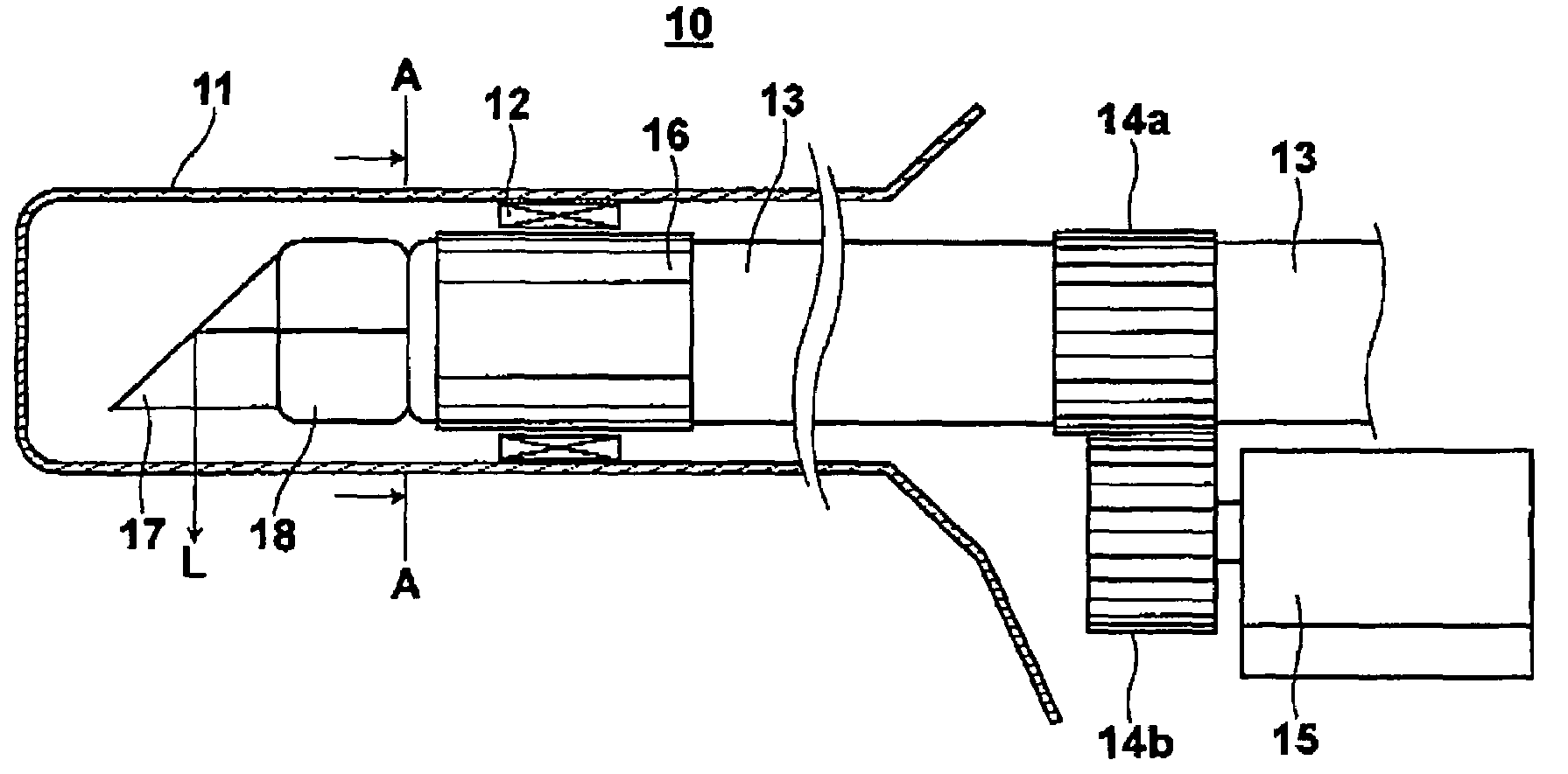
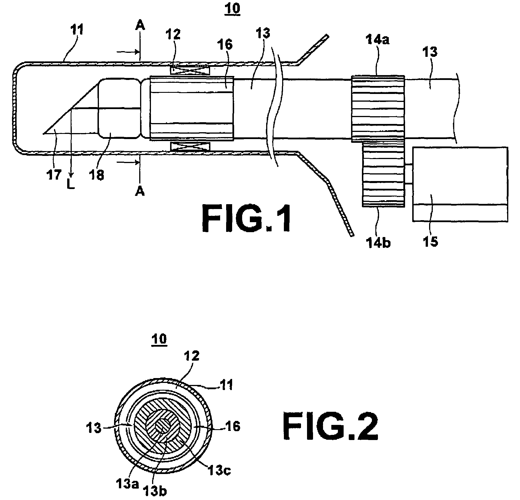
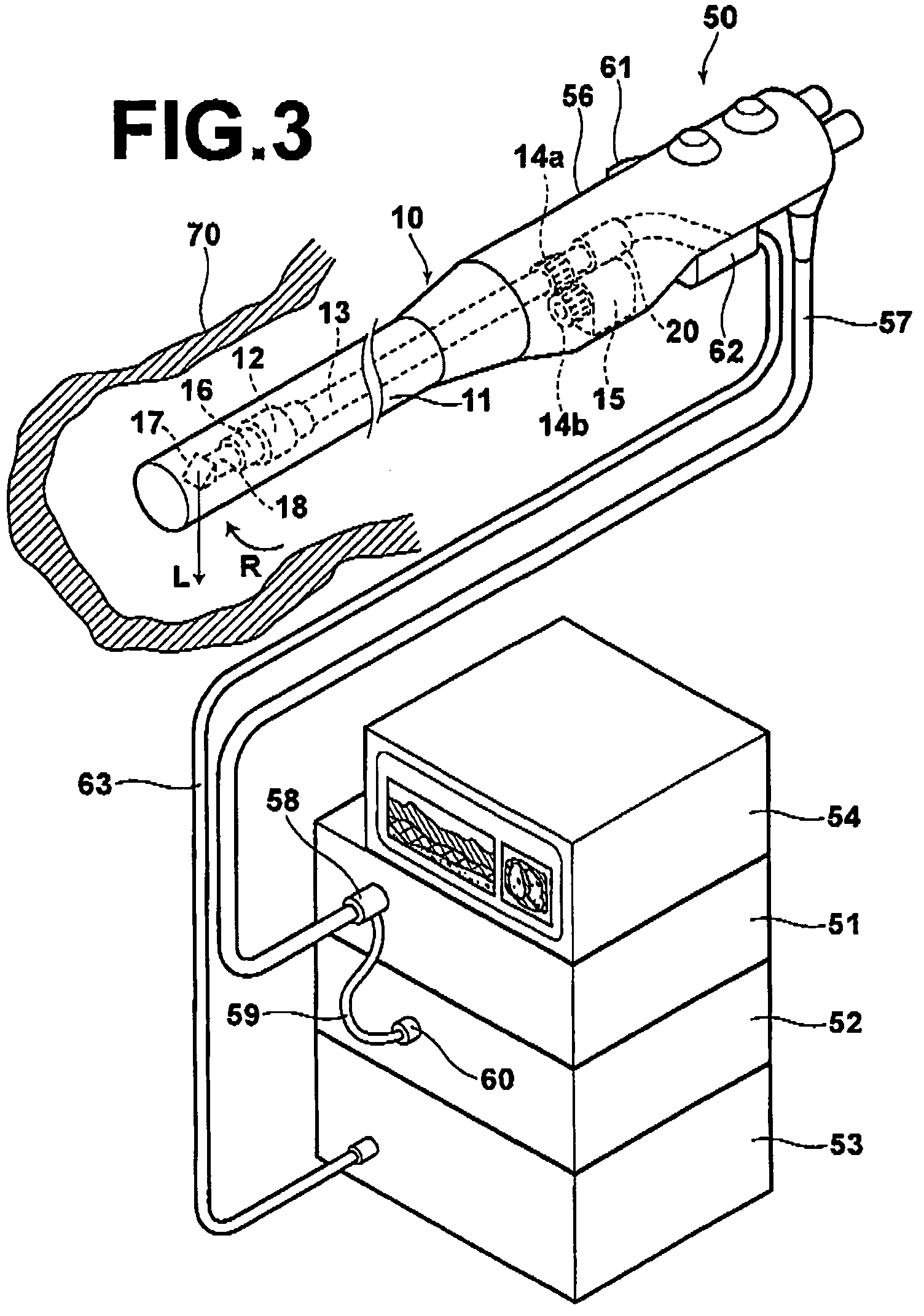
[0046]Embodiments of the present invention will be described in detail with reference to the drawings, hereinbelow. FIG. 1 shows a side cross-sectional shape of an optical probe 10 in accordance with a first embodiment of the present invention and FIG. 2 is a front cross-sectional view of the optical probe 10 taken along line A-A in FIG. 1. For example, the optical probe 10 forms a front end portion of an endoscope which forms a part of an optical tomography system. FIG. 3 shows an entire shape of the optical tomography system.

[0047]The optical tomography system will be first described in brief with reference to FIG. 3. The system comprises an endoscope 50 including the optical probe 10; a light source unit 51, a video processor 52, and an optical tomographic processing system 53 to which the endoscope 50 is connected; and a monitor 54 connected to the video processor 52. The endoscope 50 comprises an outer envelope 11 which is flexible and elongated, a control portion 56 connected ...


PUM


Abstract

An optical probe includes a tubular outer envelope and a optical fiber which extends in the longitudinal direction of the outer envelope inside the outer envelope. By fixing a light deflecting element to the optical fiber and rotating the optical fiber by a driver, the light deflecting element is rotated. A protective member which has a higher resistance to wear than the outer peripheral surface of the optical fiber is fixed to a part of the outer peripheral surface of the optical fiber in a position near the front end of the optical fiber and is borne for rotation by a bearing portion on the probe outer envelope.

Description

BACKGROUND OF THE INVENTION[0001]1. Field of the Invention[0002]This invention relates to an optical probe, and more particularly to an optical probe having a tubular outer envelope and having a function of deflecting light emitted from the peripheral surface thereof in the direction of circumference or the axis of the outer envelope. The present invention also relates to an optical tomography system where such an optical probe is employed.[0003]2. Description of the Related Art[0004]As a conventional method for obtaining tomographic images of measurement targets, such as living tissue, a method that obtains optical tomographic images by OCT (Optical Coherence Tomography) measurement has been proposed (refer to Japanese Unexamined Patent Publication Nos. 6(1994)-165784 and 2003-139688). The OCT measurement is a type of light interference measurement method that utilizes the fact that light interference is detected only when the optical path lengths of divided light beams, that is, a...

Claims


Application Information

Patent Timeline
Patent Type & Authority Patents(United States)
IPC IPC(8): G02B6/00G02B6/12
CPCG01J3/4535G01N21/4795A61B5/0059A61B5/0066G01N21/954G01N2021/9548
Inventor TERAMURA, YUICHIHATORI, MASAMI
Owner FUJIFILM CORP
Why Eureka
Try Eureka