Observation apparatus and observation system

a technology of observation apparatus and observation system, which is applied in the field of observation system, can solve the problems of high cost, difficult application of wdm system, and deterioration of reliability, and achieve the effects of high robustness system, and reducing the number of optical fibers

Inactive Publication Date: 2009-05-26
MITSUBISHI ELECTRIC CORP +1
View PDF18 Cites 4 Cited by
  • Summary
  • Abstract
  • Description
  • Claims
  • Application Information

AI Technical Summary

Benefits of technology

[0008]A main object of the present invention is to solve the above problems. Therefore, it is one of objects to cut down the system cost by reducing the number of optical fibers in the optical submarine cable. Moreover, it is one of the objects to structure an observation system where robustness is enhanced by enabling an observation signal to be transmitted to either one of the land terminal apparatuses even when a failure, such as cutting of an optical submarine cable, occurs. Furthermore, it is one of the objects to provide an observation system having high extensibility and reliability where various optical transmission methods can be used.
[0019]According to the present invention, since a signal modulated by using an observation signal is transmitted back to a management apparatus, when the channel between the management apparatus and the observation apparatus is an optical submarine cable, the system cost-down can be realized by reducing the number of optical fibers in the optical submarine cable, based on applying the WDM system. Besides, a high robustness system can be structured since the observation signal can be transmitted to either one of the land terminal apparatuses even when a failure, such as cutting of an optical submarine cable, occurs. Moreover, high reliability can be secured especially by utilizing a modulation method which uses the optical amplifier practically used in the optical submarine cable system for communication, in the submarine observation.

Problems solved by technology

Then, if the optical fiber is individually used for each of the observation equipment expected to be installed, it has a problem of causing high cost.
Consequently, the apparatus scale expands or the reliability deteriorates, which causes a problem that applying the WDM system becomes difficult.

Method used


Image

  • Observation apparatus and observation system
  • Observation apparatus and observation system
  • Observation apparatus and observation system

Examples


embodiment 1

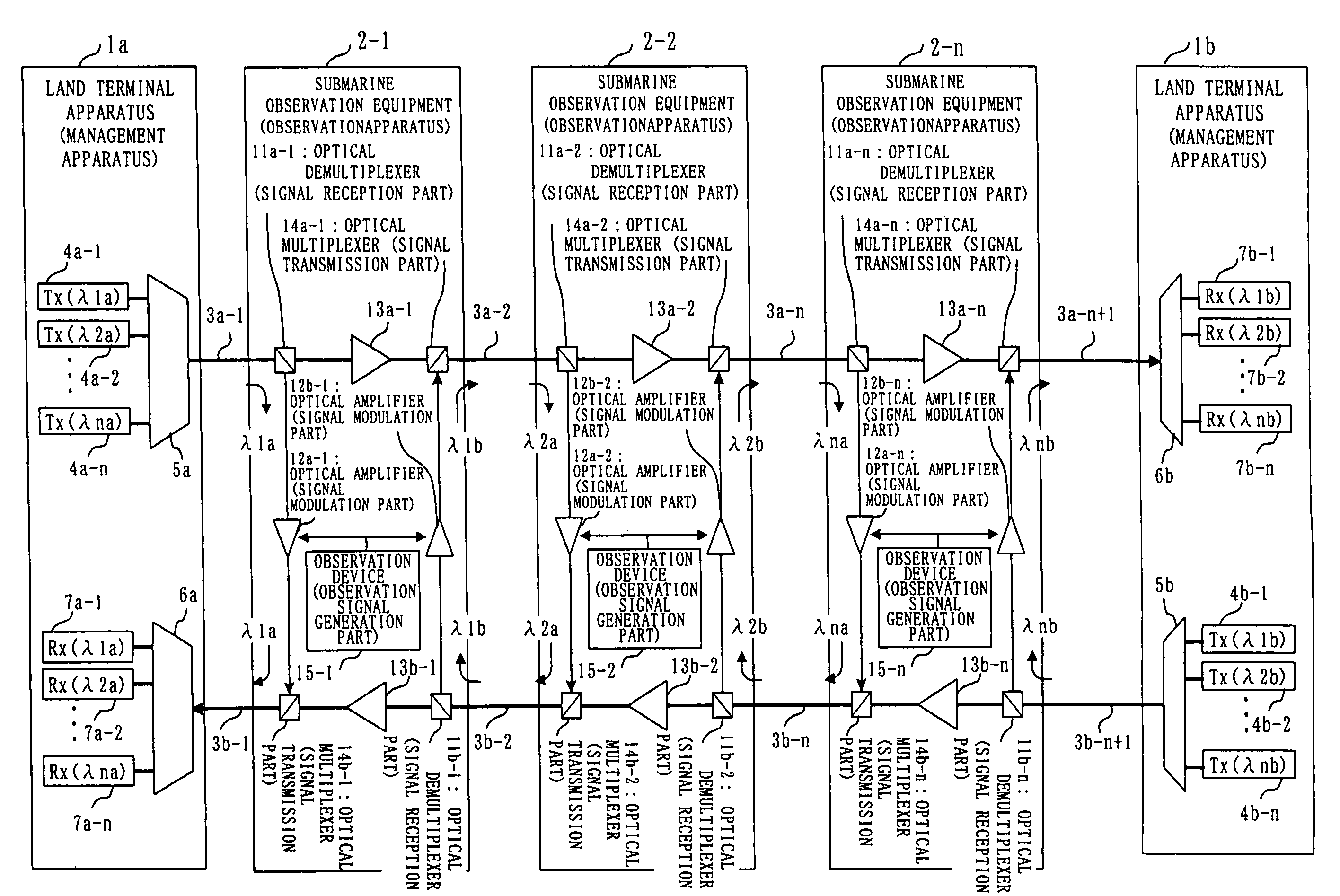
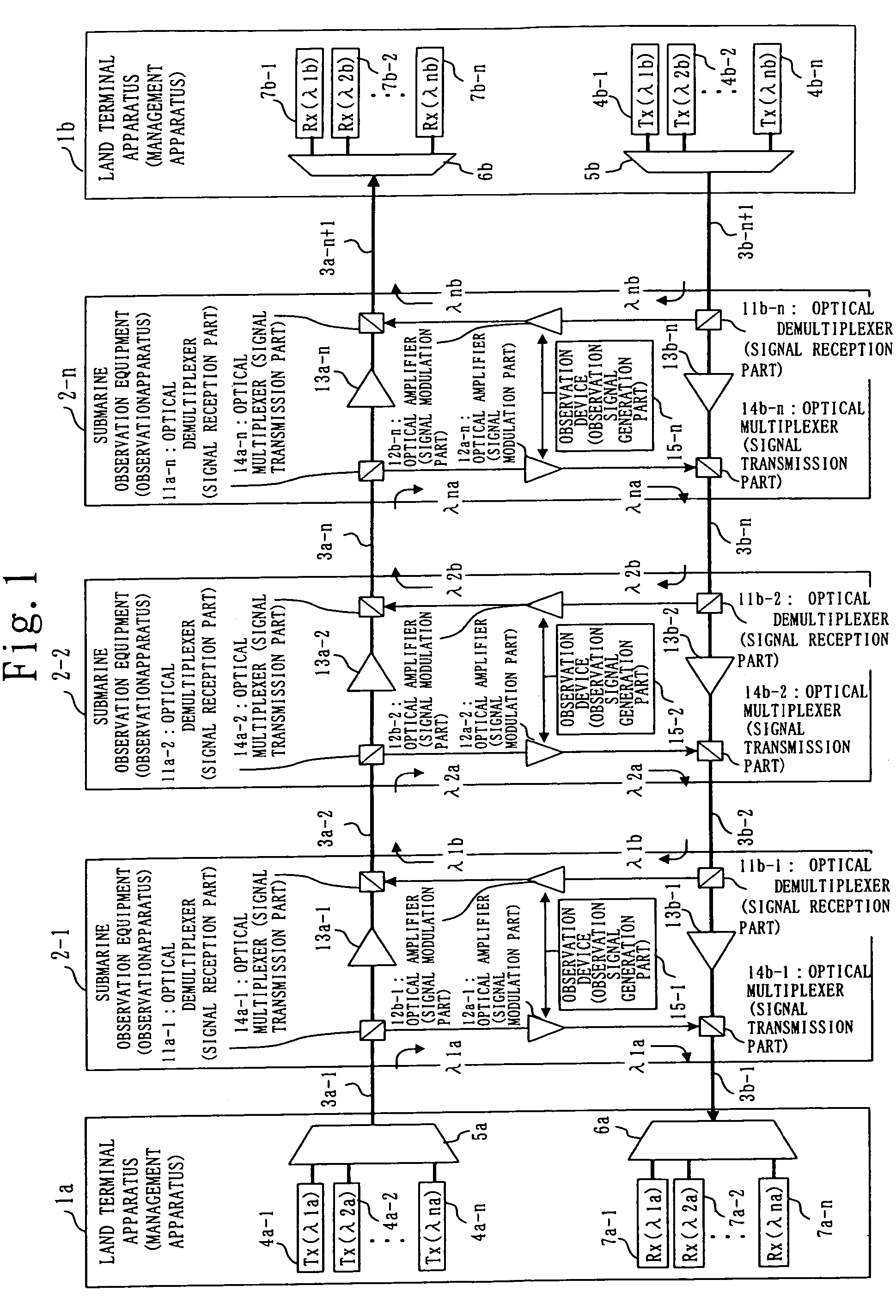
[0027]The submarine observation system according to Embodiment 1 will now be explained with reference to drawings. FIG. 1 is a structure figure showing an example of the submarine observation system according to Embodiment 1.

[0028]As shown in FIG. 1, the submarine observation system according to Embodiment 1 is composed of two land terminal apparatuses 1a and 1b, n submarine observation equipment 2-1 to 2-n in cascading connection (n is an line) (second transmission line) for respectively connecting the land terminal apparatus 1 and the submarine observation equipment 2. Each of the n submarine observation equipment 2-1 to 2-n is cascadingly connected by the optical submarine cable. One pair of the optical submarine cables composed of the down-going line and the up-going line is called one fiber pair. The optical submarine cable of one fiber pair functionally means two optical submarine cables, namely the one from the land terminal apparatus 1a to 1b and the other from the land term...

embodiment 2

[0050]Next, the submarine observation system according to Embodiment 2 will be explained. FIG. 5 is a structure figure showing an example of the submarine observation system according to Embodiment 2. Compared with the system shown in FIG. 1, the structure of FIG. 5 is the same as that of FIG. 1 except for a subcarrier generation source (frequency signal generation part) 22 and an observation signal modulation part 21 provided in the submarine observation equipment 2, and an optical transmitter 20 and an optical receiver 23 for subcarrier modulation provided in the land terminal apparatus 1.

[0051]Next, operations will be explained with reference to FIG. 5. Operations of the first set, i.e. the submarine observation equipment of n=1 will be explained as an example. In an optical transmitter 20a-1 of the land terminal apparatus 1a, the carrier light λ1a including a command signal for controlling the submarine observation equipment 2-1 is subcarrier-modulated by using a predefined freq...


PUM


Abstract

The present invention discloses a submarine observation system in which a plurality of carrier lights assigned to each submarine observation equipment is transmitted from a land terminal apparatus to an optical submarine cable (down-going) by using a WDM transmission. In the submarine observation equipment, only a prescribed carrier light is demultiplexed by an optical demultiplexer, an observation signal indicating an observation result is generated by an observation device, intensity of the carrier light demultiplexed by the optical demultiplexer is modulated by an optical amplifier based on an observation signal, and the modulated carrier light is multiplexed by an optical multiplexer. The multiplexed carrier light is output to the optical submarine cable (up-going) to be returned to the land terminal apparatus being the transmission station. The land terminal apparatus is able to obtain an observation signal of each observation point by separating carrier lights based on each wavelength and receiving a separated carrier light of each wavelength. Accordingly, the system can be structured with one optical fiber and can be extendable by increasing or decreasing carrier lights, and either one of the land terminal apparatuses can receive an observation signal even when the optical submarine cable is cut off.

Description

BACKGROUND OF THE INVENTION[0001]1. Field of the Invention[0002]The present invention relates to an observation system, and in particular, relates to technology for transmitting observation signals (data indicating observation results, such as vibrations caused by an earthquake, water pressure changes due to tsunami) acquired by submarine observation, through an optical fiber cable, for example.[0003]2. Description of the Related Art[0004]In a conventional submarine observation system, an observation signal can be transmitted to a land terminal apparatus from a submarine observation equipment even when an optical submarine cable is cut off. Moreover, for the purpose of enhancing utilization efficiency of the optical fiber of the optical submarine cable, the conventional submarine observation system has a structure where each of a plurality of submarine observation equipment outputs observation optical signals from two ports to two different optical fibers at the same time, and the o...

Claims


Application Information

Patent Timeline
Patent Type & Authority Patents(United States)
IPC IPC(8): H04B10/08H04B10/00H04B10/02G08C15/04G01D21/00G01V1/22G08C19/00G08C23/04G08C25/00H04B10/03H04B10/035H04B10/075H04B10/278H04B10/297H04J14/00H04J14/02
CPCH04B10/0771H04B10/291H04B2210/078H04B2210/074
Inventor MUNEHIRA, HIROAKINAKAGAWA, JUNICHITOKURA, TOSHIYUKIASAKAWA, KENICHIMIKADA, HITOSHIKAWAGUCHI, KATSUYOSHI
Owner MITSUBISHI ELECTRIC CORP
Why Eureka
Try Eureka