
Sensor for detecting particles

a technology of detecting particles and sensors, which is applied in the direction of instruments, specific gravity measurement, machines/engines, etc., can solve the problems of interfering with the measurement effect, and the soot sensor of the type described above is susceptible to breakdown

Inactive Publication Date: 2009-06-09
ROBERT BOSCH GMBH
View PDF19 Cites 46 Cited by
  • Summary
  • Abstract
  • Description
  • Claims
  • Application Information

AI Technical Summary

Benefits of technology

[0006]The sensor according to the present invention for detecting particles in a gas flow, in particular soot particles in an exhaust gas flow in which sensor the measuring electrodes are covered by a protective layer, has the advantage that the electrodes are protected from corrosion in the event of harsh ambient temperatures in particular.
[0007]Furthermore, in the sensor according to the present invention, contamination of the sensitive area now formed by the protective layer by undesired materials may be prevented through a suitable material selection and the cross sensitivity of the sensor may thus be reduced.
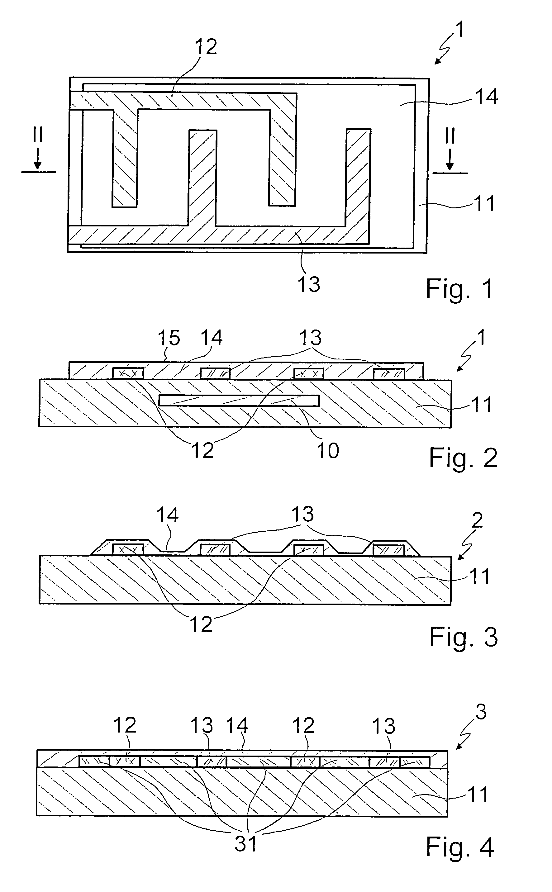
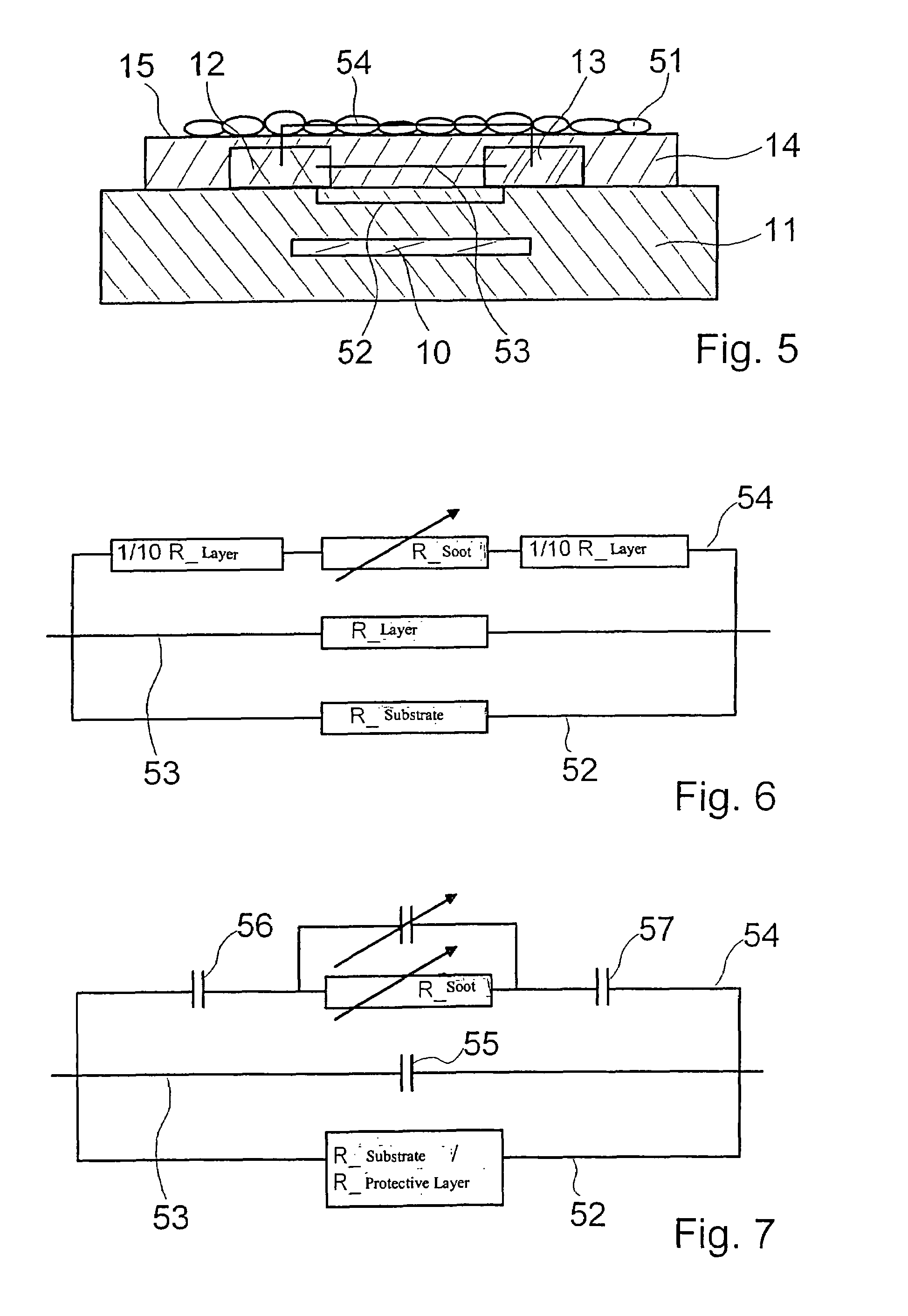
[0013]It is advantageous if the material of the insulating protective layer has a high dielectric constant and a low thickness. The high capacitance resulting therefrom allows the measurement of an impedance signal dominated by the particle covering even at low measurement frequencies.
[0014]In this way, capacitive interference currents which are caused by the capacitance of the substrate are suppressed. Materials which are used for ceramic capacitors, such as doped BaTiO3, are advantageous here.
[0015]Particularly favorable measurement results may be achieved if the electrodes are positioned as interdigital comb electrodes on a surface of the substrate. The protective layer then advantageously covers the entire area of the substrate, its thickness being selected at least in the area of the at least two electrodes in such a way that it is at most one-tenth of the distance between the two measuring electrodes. It is thus ensured during operation of the sensor that the electrical conductivity of the sensor area between the two electrodes is essentially predefined by the amount of particles on the protective layer. The protective layer area between the electrodes and the surface of the protective layer has, because of its low thickness, that the resistance between the interdigitals is high in the absence of soot particles. In addition, however, the resistance between the particle, i.e., soot layer, and the interdigital electrodes is low. A favorable ratio between the base signal, in the absence of particles or soot, and the measured signal, in the presence of particles or soot, is thus obtained.
[0019]Furthermore, it is advantageous in regard to the material selection if the substrate is manufactured from a highly insulating material, for example, from a ceramic such as aluminum oxide.

Problems solved by technology

Since the electrodes are subjected directly to the exhaust gas flow, in this known sensor corrosion of the electrodes and contamination of the sensor surface with materials may disadvantageously occur, which may have an interfering effect on the measurement.
A soot sensor of the type described above is susceptible to breakdown under the conditions existing in the exhaust system, however.

Method used


Image

  • Sensor for detecting particles
  • Sensor for detecting particles
  • Sensor for detecting particles

Examples


Embodiment Construction

[0029]A sensor 1 for detecting particles in a gas flow is illustrated in FIGS. 1 and 2. Sensor 1 is used for installation in an exhaust system of a motor vehicle and is preferably positioned downstream from a soot filter of a motor vehicle having a diesel engine.

[0030]Sensor 1 includes a plate-like carrier layer 11, used as the substrate, which is manufactured from a highly insulating material, for example, from a ceramic such as aluminum oxide. It is also conceivable to manufacture carrier layer 11 from an alternative material, such as yttrium-stabilized zirconium dioxide. At high operating temperatures, an additional insulation layer may be necessary for insulation.

[0031]A heating element 10, which is only illustrated symbolically here and which is used for burning sensor 1 free of possibly accumulated particles, such as soot particles, is integrated into carrier layer 11.

[0032]A structure made of two interdigital comb electrodes 12 and 13, which are manufactured from platinum Pt ...


PUM

PropertyMeasurementUnit
operating temperaturesaaaaaaaaaa
insulatingaaaaaaaaaa
resistanceaaaaaaaaaa

Abstract

A sensor for detecting particles in a gas flow, in particular soot particles in an exhaust gas flow, includes at least two measuring electrodes, which are positioned on a substrate made of an insulating material. To protect the measuring electrodes, they are covered by a protective layer.

Description

FIELD OF THE INVENTION[0001]The present invention is directed to a sensor for detecting particles in a gas flow, in particular soot particles in an exhaust gas flow.BACKGROUND INFORMATION[0002]A sensor of this type is known from practice and is used, for example, for determining the soot concentration of an exhaust gas of a diesel engine. This sensor forms a resistive particulate sensor in which at least two electrodes are positioned on a substrate which is manufactured from aluminum oxide or yttrium-stabilized zirconium dioxide having an insulation layer, for example. The electrodes may be implemented as interdigital comb electrodes. Soot particles which accumulate in the area between electrodes short-circuit the electrodes, through which a decreasing electrical resistance between the electrodes is measurable as the particle and / or soot concentration on the sensor surface increases.[0003]Since the electrodes are subjected directly to the exhaust gas flow, in this known sensor corro...

Claims


Application Information

Patent Timeline
Patent Type & Authority Patents(United States)
IPC IPC(8): G01N7/00F01N11/00
CPCG01N15/0656F01N2560/05F01N2560/20
Inventor BERGER, JOACHIMSTROHMAIER, RAINERHEIMANN, DETLEFBREUER, NORBERTWIRTH, RALFREINHART, KARL-FRANZSCHMIDT, RALFBAUER, WALTERBALDENHOFER, KAI-ACHIMKAMP, BERNARDGRAU, THOMAS
Owner ROBERT BOSCH GMBH
Learn More