Nano-patch thermal management devices, methods, & systems

a technology of thermal management device and nano-patch, applied in the direction of power cables, cables, lighting and heating apparatus, etc., can solve the problems of inefficient operation, excessive heat generation, and increasing temperature of chips,

Inactive Publication Date: 2009-06-09
GEORGIA TECH RES CORP
View PDF9 Cites 20 Cited by
  • Summary
  • Abstract
  • Description
  • Claims
  • Application Information

AI Technical Summary

Benefits of technology

[0010]Still yet, some embodiments of the present invention include a system to transfer and manage thermal energy released at a hot spot on a surface of a chip. Such a perspirating patch thermal management system can generally comprise a liquid in a cavity, a gas conduit, and a perspirating patch. The cavity can be proximate a hot spot, and configured and shaped to control the thickness of the liquid within the cavity. The liquid is preferably at a temperature lower than the temperature of the hot spot enabling the liquid to absorb heat from the hot spot. The gas conduit can provide a flow of gas proximate the cavity allowing the flow of gas to pass proximate the cavity. The perspirating patch can be disposed in liquid communication with the cavity. The perspirating patch can comprise a plurality of perforated holes to advantageously receive evaporated liquid from the cavity for presentation toward the flow of gas. The flow of gas can carry the evaporated liquid from the perforated holes of the perspirating patch.
[0012]As discussed below in more detail, certain embodiments of the present invention can be implemented as micro / nano-patches. Patches are at times referred to herein as perspiring because embodiments of the present invention advantageously use liquid evaporation and selective transport through a semi-permeable membrane of a patch to manage and remove heat fluxes. Such cooling utilizes phase change (liquid-to-vapor) and heat and mass transfer, and thus has a perspiring effect on a membrane surface of a patch.

Problems solved by technology

Due to the continuing increased density of processing power per size of processing chips, the International Technology Roadmap for Semiconductors (ITRS) predicts that temperature issues associated with chips will continue to increase.
Excessive heat generation can have undesirable side effects for computer processing chips.
Such side effects include inefficient operation which in turn possibly wastes operating power, and processing chip overheating possibly leading to device failure.
Another possible problem is unwanted heat generation which can, at times, be uncomfortable or even potentially harmful to an end user.
While serving their respective purposes, these conventional techniques of solving heat problems do posses several drawbacks.
One such drawback is the inability to focus in on specific areas of heat generation (or hot spots) occurring on a chip.
Similarly, another drawback is that the size of conventional techniques does not enable thermal management at lower scale locations (e.g., micro-scale or nano-scale) using easily controlled techniques.
And yet another drawback is the limited magnitude of a heat flux (per unit area) that can be removed using conventional cooling techniques, and thermal problems associated with high performance electronic chips.

Method used


Image

  • Nano-patch thermal management devices, methods, & systems
  • Nano-patch thermal management devices, methods, & systems
  • Nano-patch thermal management devices, methods, & systems

Examples


Embodiment Construction

[0021]Referring now to the figures, wherein like reference numerals represent like parts throughout the several views, exemplary embodiments of the present invention will be described in detail. Throughout this description, various components may be identified having specific values or parameters, however, these items are provided as exemplary embodiments. Indeed, the exemplary embodiments do not limit the various aspects and concepts of the present invention as many comparable parameters, sizes, ranges, and / or values may be implemented.

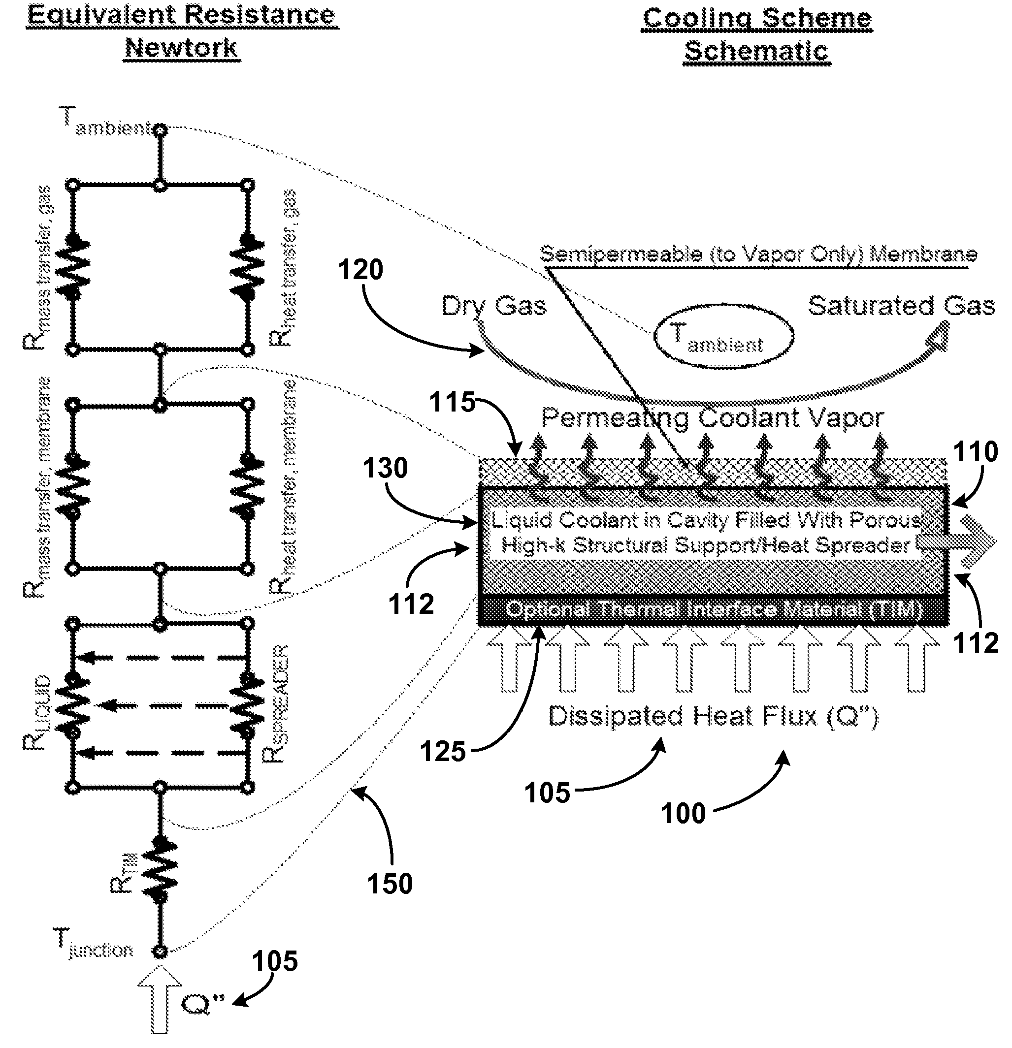
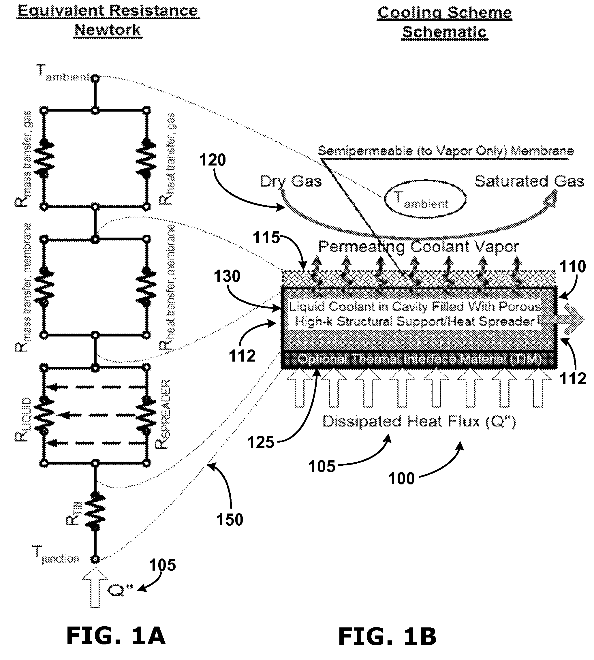
[0022]Phase change heat transfer is an efficient means of heat transfer due to an advantage offered by the significant latent heat of vaporization of liquids. In other words, for example, the amount of energy to convert liquid water to steam (or water vapor) is high thus providing an efficient means of transferring heat between locales. There are two methods to enable phase change heat transfer: boiling and evaporation. A key difference between boili...


PUM


Abstract

Nano-scale thermal management devices, methods, and systems are provided. According to some embodiments, a thermal management device configured to remove heat from a heated area can comprise an inlet port and a cavity. The cavity can be positioned intermediate a heat source and an opposing surface spaced apart from the heat source. The inlet port can receive a liquid (such as a coolant or cooling fluid) and direct the liquid to the cavity. The cavity can be configured to control the thickness of the liquid within the cavity. Liquid within the cavity can be heated by the heat source, and the opposing surface can comprise openings to allow evaporated liquid to exit the openings. A gas flow proximate the opposing surface can be used to carry vapor and be used to enhance liquid evaporation. Movement of the evaporated liquid enables heat from the heat source to be removed. The opposing surface can be a perforated membrane having micro-sized and nano-sized perforations. Other embodiments are also claimed and described.

Description

CROSS REFERENCE TO RELATED APPLICATION & PRIORITY CLAIM[0001]This patent application claims priority to and the benefit of U.S. Provisional Application No. 60 / 800,594 filed on 16 May 2006, and entitled “Perspirating nano-patch for hot spot thermal management,” which is hereby incorporated by reference as if fully set forth below in its entirety.TECHNICAL FIELD[0002]The various embodiments of the present invention relate generally to thermal management devices and techniques, and more particularly, to micro-scale and nano-scale thermal management devices, methods, and systems.BACKGROUND[0003]Due to the continuing increased density of processing power per size of processing chips, the International Technology Roadmap for Semiconductors (ITRS) predicts that temperature issues associated with chips will continue to increase. Indeed, the ITRS predicts that the allowable maximum power dissipated for high-performance and cost-effective microprocessor units (MPU) is going to increase steadi...

Claims


Application Information

Patent Timeline
Patent Type & Authority Patents(United States)
IPC IPC(8): H05K7/20
CPCH01L23/427H01L2924/0002H01L2924/00
Inventor FEDOROV, ANDREI G.
Owner GEORGIA TECH RES CORP
Why Eureka
Try Eureka