Comb sense microphone

a comb sense and microphone technology, applied in the direction of electrical transducers, piezoelectric/electrostrictive transducers, transducer types, etc., can solve the problem of limiting the practical upper limit of bias voltage vb, diaphragm stiffness conflicts, and distortion of output signals relative to the sensed acoustic pressure typically, etc. problem, to achieve the effect of low noise, high output voltage and easy formation

Inactive Publication Date: 2009-06-09
RES FOUND OF THE STATE THE
View PDF13 Cites 31 Cited by
  • Summary
  • Abstract
  • Description
  • Claims
  • Application Information

AI Technical Summary

Benefits of technology

[0019]In accordance with the present invention there is provided an ultra-miniature microphone incorporating a rigid silicon resiliently supported substrate which forms a diaphragm. A series of fingers disposed around the perimeter of the diaphragm interacts with mating fingers disposed adjacent the diaphragm fingers with a small gap in between. In other words, the fingers are interdigitated. The movement of the diaphragm fingers relative to the fixed fingers varies the capacitance, thereby allowing creation of an electrical signal responsive to a varying sound pressure at the diaphragm. Because the electrostatic force on the fingers does not have a significant dependence on the out-of-plane displacement of the diaphragm, the classic problem of attraction of the diaphragm to the back plate discussed hereinabove is effectively overcome. The diaphragm can be designed to be very compliant without creating instabilities due to electrostatic forces. The multiple fingers allow creation of a microphone having a high output voltage relative to microphones of the prior art. This, in turn, allows creation of very low noise microphones.
[0020]The diaphragm is readily formed using well-known silicon microfabrication techniques to yield low manufacturing costs.
[0021]It should be noted that many capacitive sensors utilize interdigitated comb fingers. The primary uses of this sensing approach are in silicon accelerometers and gyroscopes well known to those of skill in those arts. Such sensors generally consist of a resiliently supported proof mass that moves relative to the surrounding substrate due to the motion of the substrate. An essential feature of these constructions is that the proof mass is supported only on a small fraction of its perimeter, allowing a significant portion of the perimeter to be available for capacitive detection of the relative motion of the proof mass and the surrounding substrate through the use of comb fingers. This requirement has precluded the use of comb fingers for capacitive sensing in microphones because the typical approach to the formation of a microphone diaphragm is to construct a very thin plate that is effectively clamped along its entire perimeter. Because silicon accelerometers and gyroscopes utilize compliant hinges rather than entirely clamped perimeters, they readily permit the use of comb fingers for sensing.

Problems solved by technology

This limits the practical upper limit of the bias voltage Vb.
Unfortunately, this requirement for diaphragm stiffness conflicts with the need for high diaphragm compliance necessary to ensure responsiveness to sound pressure.
Because in microphones of this construction, electrostatic force f does not vary linearly with x, distortion of the output signal relative to the sensed acoustic pressure typically results.
Yet another problem occurs in these types of microphones.

Method used


Image

  • Comb sense microphone
  • Comb sense microphone
  • Comb sense microphone

Examples


Embodiment Construction

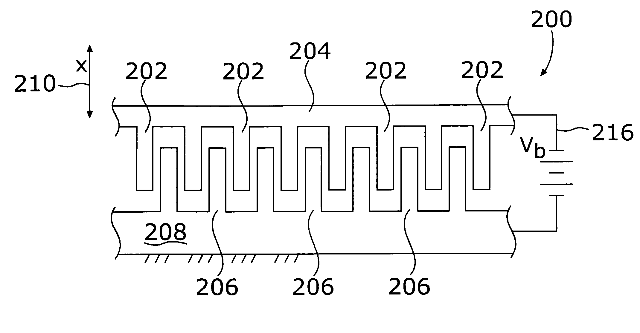
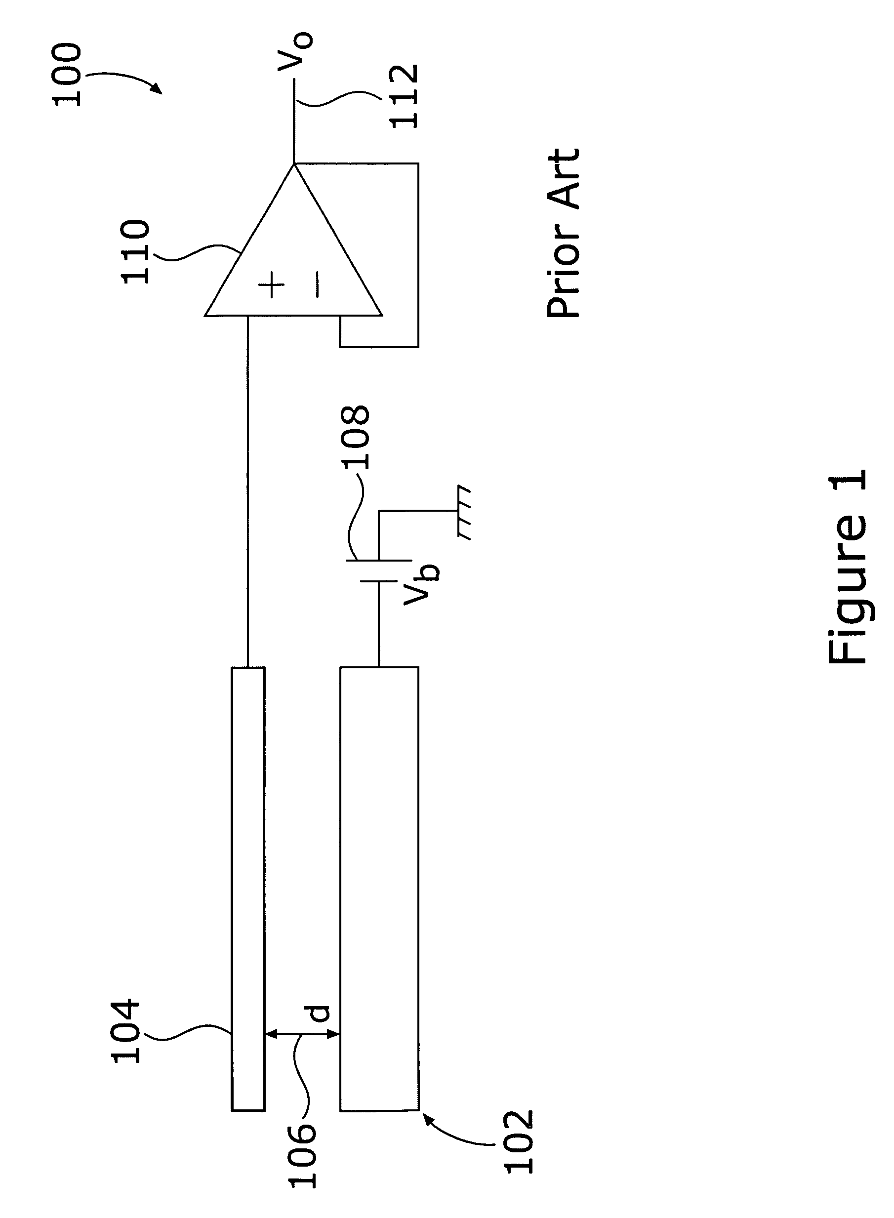
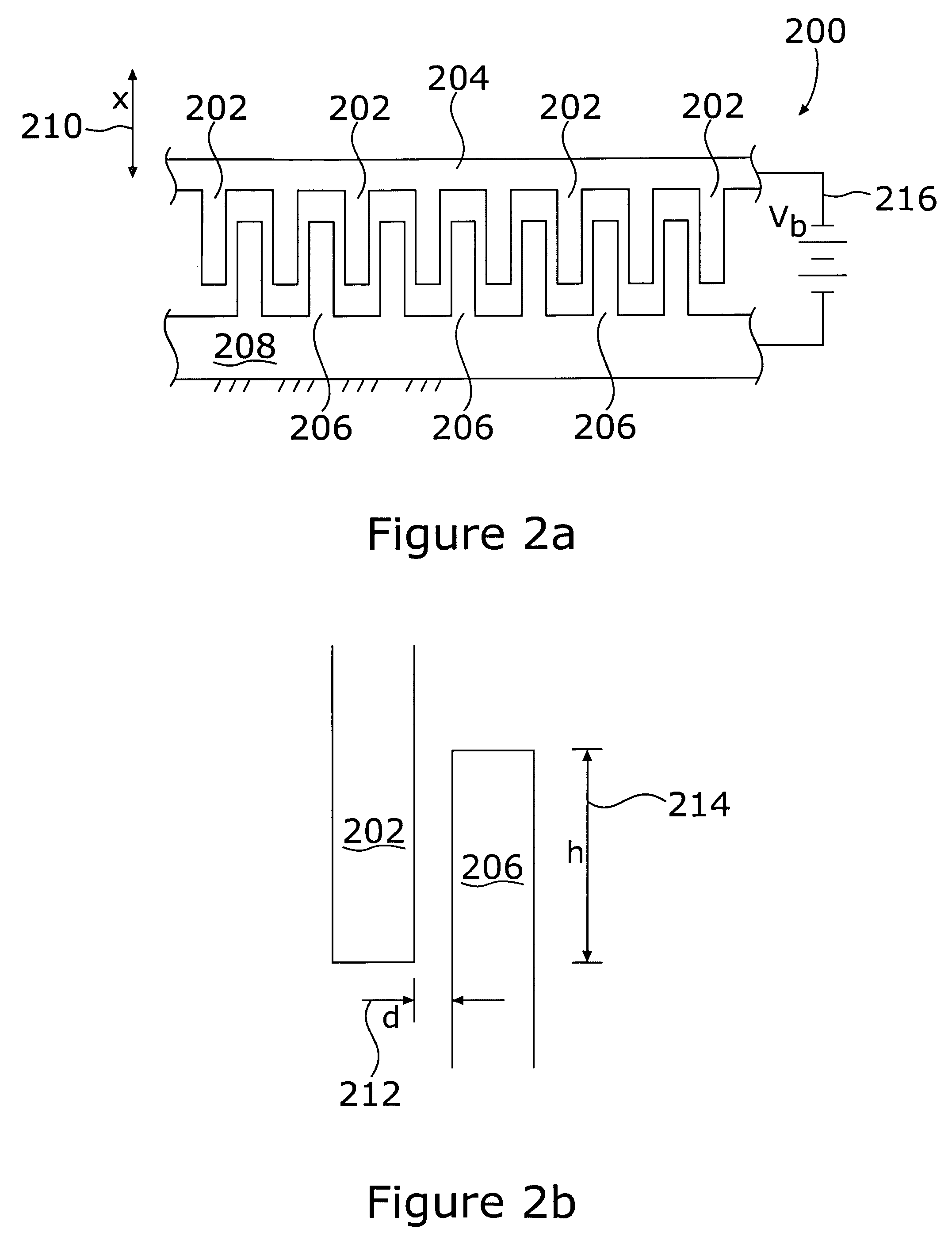
[0033]A highly efficient capacitance microphone that overcomes the deficiencies of classic capacitance microphones of the prior art described hereinabove may be formed by making a diaphragm having a series of fingers disposed around its perimeter. These fingers are then interdigitated with corresponding fingers on a fixed structure analogous to a back plate in microphone 100 (FIG. 1).

[0034]Referring now to FIG. 2a, there is shown a schematic cross-sectional view of an interdigitated finger structure, generally at reference number 200. A series of fingers 202 projects from the surface of a substrate 204. The surface of substrate 204 is free to move out of the plane of the figure and forms the diaphragm of a microphone. Additional fingers 206 project from the surface of a fixed structure 208 representative of a microphone back plate. Fingers 202 projecting from diaphragm 204 are free to move with the diaphragm out of the plane of the figure as well as in the direction x indicated by a...


PUM


Abstract

There is provided a rigid hinged substrate, which forms a diaphragm for miniature microphones. A series of fingers disposed radially around the perimeter of the diaphragm interacts with mating fingers disposed adjacent the diaphragm with a small gap in between. The fingers are interdigitated. The movement of the diaphragm fingers relative to the fixed fingers varies the capacitance, thereby allowing creation of an electrical signal responsive to varying sound pressure at the diaphragm. Because the fingers may be formed with great stiffness, the classic problem in typical capacitive microphones of attraction of the diaphragm to the back plate is effectively overcome. The multiple fingers allow the creation of a microphone having a high output voltage relative to conventional microphones. This yields a very low noise microphone. The diaphragm may be readily formed using well known silicon microfabrication techniques so as to reduce manufacturing costs.

Description

STATEMENT OF GOVERNMENT INTEREST[0001]This invention was made with Government support under R01DC005762 awarded by the National Institute of Health. The Government has certain right in the invention.RELATED APPLICATIONS[0002]This application is related to U.S. patent application Ser. No. 09 / 920,664, filed Aug. 1, 2001, titled DIFFERENTIAL MICROPHONE, now issued as U.S. Pat. No. 6,788,796, and application Ser. No. 10 / 302,528 filed Nov. 25, 2002, titled ROBUST DIAPHRAGM FOR AN ACOUSTICAL DEVICE and U.S. patent application Ser. No. 10 / 691,059, filed Oct. 22, 2003, titled HIGH-ORDER DIRECTIONAL MICROPHONE DIAPHRAGM, all of which are included herein in their entirety by reference.FIELD OF THE INVENTION[0003]The invention pertains to capacitive microphones and, more particularly to capacitive microphones having rigid, silicon diaphragms with a plurality of fingers interdigitated and interacting with corresponding fingers of an adjacent, fixed frame.BACKGROUND OF THE INVENTION[0004]A commo...

Claims


Application Information

Patent Timeline
Patent Type & Authority Patents(United States)
IPC IPC(8): H04R25/00
CPCH04R19/04
Inventor MILES, RONALD
Owner RES FOUND OF THE STATE THE
Why Eureka
Try Eureka