Two phase injector for fluidized bed reactor

a technology of fluidized bed reactor and injector, which is applied in sustainable manufacturing/processing, lighting and heating apparatus, furniture, etc., can solve the problems of unsuitable most uses without further purification, large commercial units, and large amount of “methane slips, and achieves the problem of separating the feed stream of entrained calcium-oxide-particles in multiples (i.e., on the order of 6 to 36)

Active Publication Date: 2009-06-16
THE BOEING CO +2
View PDF36 Cites 41 Cited by
  • Summary
  • Abstract
  • Description
  • Claims
  • Application Information

AI Technical Summary

Benefits of technology

[0014]In accordance with the present invention, apparatus is provided for uniformly and reliably splitting a stream of entrained calcium oxide particles into multiple feed streams, and then injecting those streams, together with the steam / methane gas mixture reactants, into the fluidized bed of a steam / methane reactor such that a very uniform distribution and rapid mixing of both the solid calcium oxide particles and the steam / methane gas mixture is achieved across the entire bottom of the fluidized bed of the reactor.

Problems solved by technology

However, these commercial units tend to be extremely large and subject to significant amounts of “methane slip,” i.e., methane feedstock that passes through the reformer unreacted.
The presence of such methane (and other reactants or byproducts) serves to pollute the hydrogen, thereby rendering it unsuitable for most uses without further purification.
However, as this process has matured over time, certain technical issues have arisen that require resolution.
Uniform splitting of entrained calcium-oxide-particle streams into multiple (i.e., on the order of 6 to 36) feed streams is problematic in dilute, two-phase pneumatic gas flows.
This is because the reaction of the CO2 with the calcium oxide is highly exothermic, and can potentially lead to local, destructive “hot zones” if not accurately counterbalanced by the highly endothermic methane / steam reaction.

Method used


Image

  • Two phase injector for fluidized bed reactor
  • Two phase injector for fluidized bed reactor
  • Two phase injector for fluidized bed reactor

Examples


Embodiment Construction

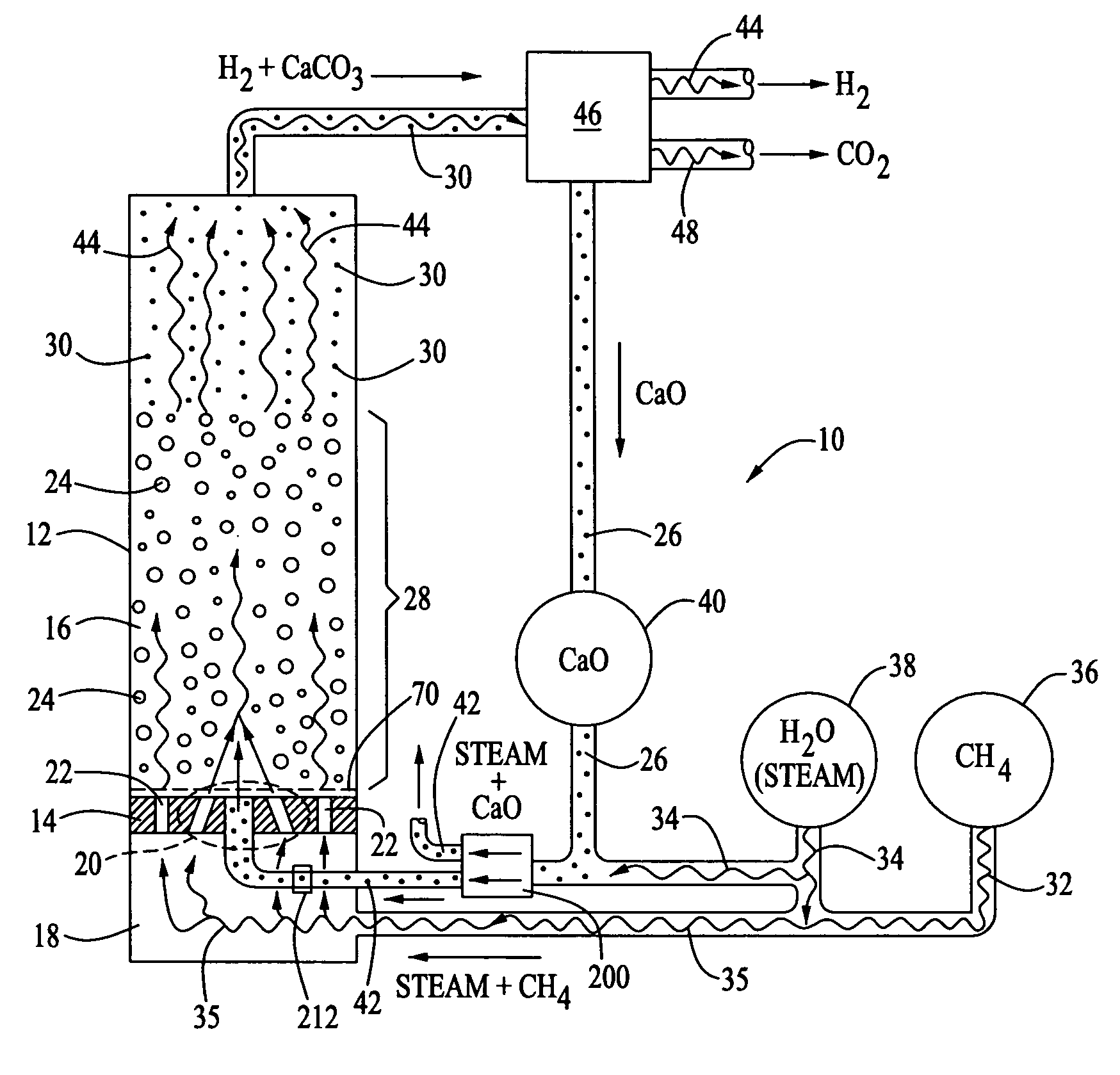
[0026]A schematic, cross-sectional elevation view of an exemplary embodiment of a one-step, two-particle, fluidized-bed reactor 10 for the production of hydrogen from methane by a steam reforming process in accordance with the present invention is illustrated in FIG. 1. The reactor comprises an elongated, closed, vertical chamber 12. An orifice plate 14 is disposed horizontally within a lower portion of the reactor to define an upper, fluidized-bed reaction chamber 16 and a lower, pressurized-gas-manifold chamber 18, as shown. As described in more detail below, the orifice plate 14 also serves to define at least one high-velocity, “rocket-style” impinging injector 20 for injecting reactants into the fluidized-bed reaction chamber, together with a plurality of base-bleed orifices 22 disposed around the injector and extending substantially perpendicularly through the plate for injecting respective streams of reactants from the gas-manifold chamber into the fluidized-bed chamber, as de...


PUM

PropertyMeasurementUnit
axial velocityaaaaaaaaaa
pressureaaaaaaaaaa
velocityaaaaaaaaaa

Abstract

A fluidized-bed reactor for producing hydrogen from methane by steam reforming includes a flow splitter that splits a dense-phase flow of a gas having entrained calcium oxide particles into a plurality of equal flow streams. The reactor also incorporates an orifice plate having at least one high-velocity, rocket-style impinging injector for injecting reactants into the reactor bed. The injector includes a central orifice extending perpendicularly through the plate, and one or more adjacent peripheral orifices that extend through the plate at such an angle that respective streams of reactants injected into the reactor bed through the peripheral orifices impinge on a stream of reactants injected vertically into the reactor bed through the central orifice. The injector cooperates with adjacent base-bleed orifices in the plate to provide a uniform distribution and rapid mixing of the calcium oxide particles with a steam / methane gas mixture across the entire bottom of the reactor bed.

Description

CROSS-REFERENCE TO RELATED APPLICATIONS[0001]This application is related to U.S. Ser. No. 10 / 271,406, filed Oct. 15, 2002; U.S. Ser. No. 10 / 610,469, filed Jun. 30, 2003; U.S. Ser. No. 10 / 609,940, filed Jun. 30, 2003; and U.S. Ser. No. 10 / 869,643, entitled “DRY, LOW NITROUS OXIDE CALCINER INJECTOR”, U.S. Ser. No. 10 / 869,644, entitled “HOT ROTARY SCREW PUMP”, U.S. Ser. No. 10 / 869,642, entitled “SOLIDS MULTI-CLONE SEPARATOR”, AND U.S. Ser. No. 10 / 869,641, entitled “HYDROGEN GENERATION SYSTEM WITH METHANATION UNIT” filed herewith, the respective disclosures of which are incorporated herein by this reference.REFERENCE TO APPENDIX[0002](Not Applicable)BACKGROUND OF THE INVENTION[0003]1. Field of the Invention[0004]This invention relates to the large-scale production of commercially pure hydrogen gas in general, and in particular, to a dense-phase flow splitter and high-velocity, two-phase injector for use in a one-step, two-particle, fluidized-bed, steam-and-methane reactor used for such ...

Claims


Application Information

Patent Timeline
Patent Type & Authority Patents(United States)
IPC IPC(8): F27B15/08B01J8/18B05B7/04B05B7/06B65G51/18B65G51/24B01J8/44C01B3/44
CPCB01J8/1818B01J8/44C01B3/44B01J2208/00769C01B2203/0233C01B2203/0425C01B2203/0475C01B2203/1241Y02P30/00
Inventor SPROUSE, KENNETH MSTEWART, ALBERT E.
Owner THE BOEING CO
Why Eureka
Try Eureka