Collision monitoring system

a technology of collision monitoring and control system, which is applied in the direction of dynamo-electric converter control, roof, instruments, etc., can solve the problems of undesirable shutdown difficulty in design of power window control, and prior art automatic power window control operation, etc., to increase obstacle detection thresholds and resistance to movemen

Inactive Publication Date: 2009-06-16
UUSI
View PDF48 Cites 19 Cited by
  • Summary
  • Abstract
  • Description
  • Claims
  • Application Information

AI Technical Summary

Benefits of technology

[0004]Certain technical difficulties exist with operation of prior art automatic power window controls. One difficulty is undesirable shutdown of the power window control for causes other than true obstacle detection. Detection of obstacles during startup energization, soft obstacle detection, and hard obstacle detection each present technical challenges requiring multiple simultaneous obstacle detection techniques. Additionally, the gasket area of the window that seals to avoid water seepage into the vehicle presents a difficulty to the design of a power window control, since the window panel encounters significantly different resistance to movement in this region. Operation under varying power supply voltage results in actuator speed variations that result in increased obstacle detection thresholds.

Problems solved by technology

Certain technical difficulties exist with operation of prior art automatic power window controls.
One difficulty is undesirable shutdown of the power window control for causes other than true obstacle detection.
Detection of obstacles during startup energization, soft obstacle detection, and hard obstacle detection each present technical challenges requiring multiple simultaneous obstacle detection techniques.
Additionally, the gasket area of the window that seals to avoid water seepage into the vehicle presents a difficulty to the design of a power window control, since the window panel encounters significantly different resistance to movement in this region.
Operation under varying power supply voltage results in actuator speed variations that result in increased obstacle detection thresholds.

Method used


Image

  • Collision monitoring system
  • Collision monitoring system
  • Collision monitoring system

Examples


Embodiment Construction

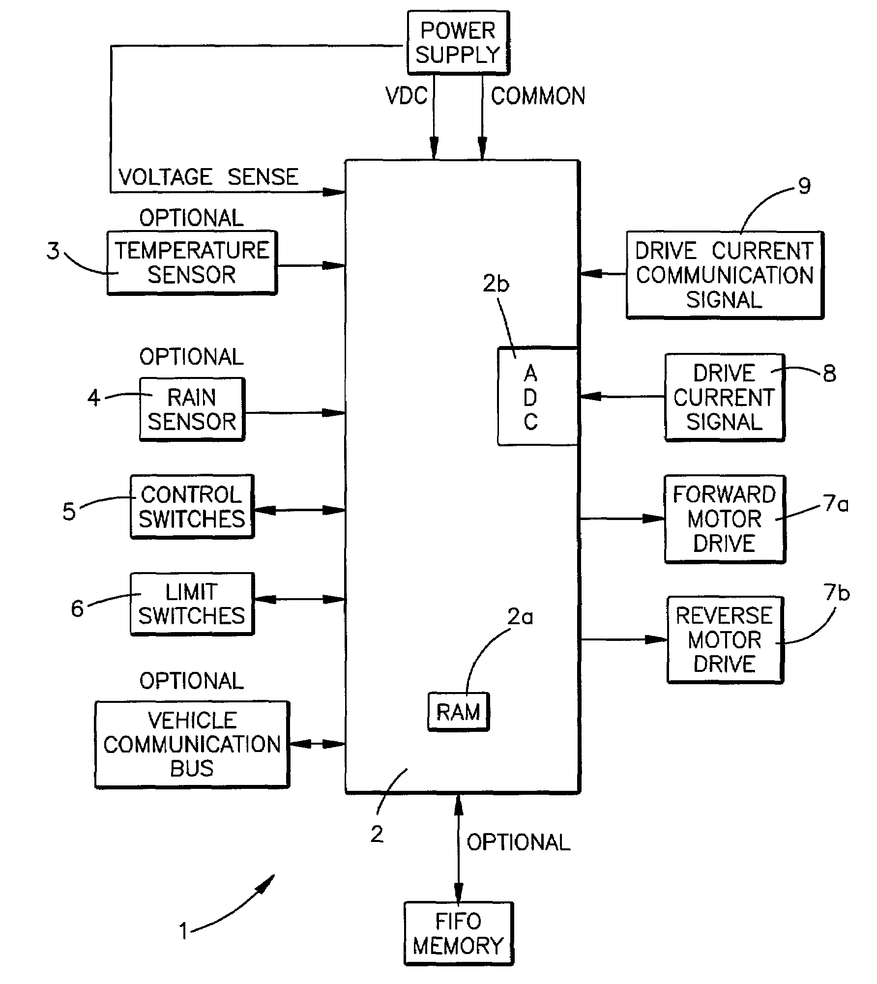
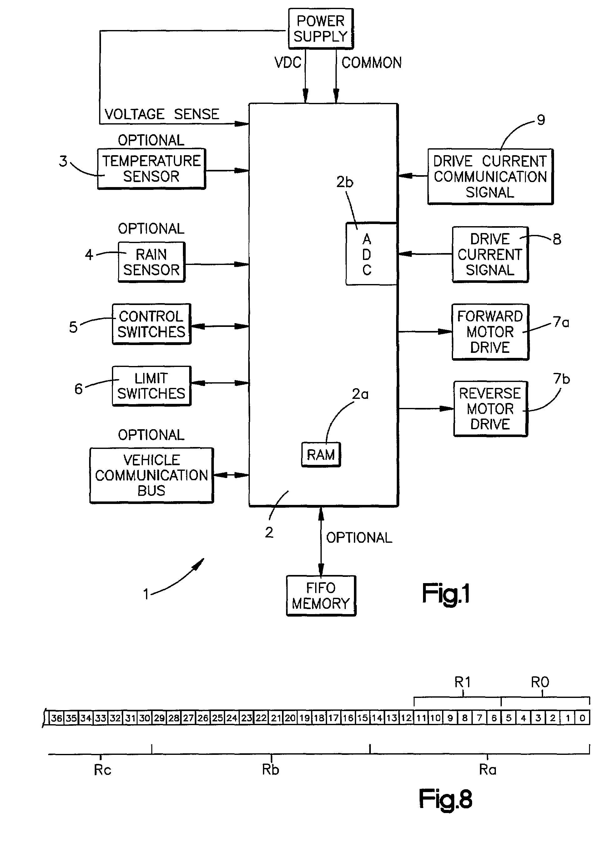
[0021]FIG. 1 shows a functional block diagram of an actuator safety feedback control system 1 for monitoring and controlling movement of a motor driven panel such as a motor vehicle sunroof. A panel movement controller 2 includes a commercially available multipurpose microcontroller IC (integrated circuit) with internal and / or external FIFO memory and / or RAM (Random Access Memory) 2a and ADC (analog-to-digital-converter) 2b.

[0022]Eight-bit word bytes, eight-bit counters, and eight-bit analog-to-digital conversions are used with the exemplary controller 2. It should be fully realized, however, that alternative word lengths may be more appropriate for systems requiring different parameter resolution. Larger word bytes with equivalent ADC resolution enables greater resolution for motor current sensing. Likewise, larger word bytes with higher microcontroller clock speeds enable greater resolution for motor per speed sensing plus quicker digital signal processing and algorithm processin...


PUM


Abstract

Disclosed is an improved system and method for sensing both hard and soft obstructions for a movable panel such as a sunroof. A dual detection scheme is employing that includes an optical sensing as the primary means and electronic sensing of motor current as a secondary means. The secondary means utilizes system empirical precharacterization, fast processing algorithms, motor parameter monitoring including both current sensing and sensorless electronic motor current commutation pulse sensing, and controller memory, to adaptively modify electronic obstacle detection thresholds in real time without the use of templates and cycle averaging techniques.

Description

CROSS REFERENCE TO RELATED APPLICATIONS[0001]The present application is a continuation-in-part of application Ser. No. 09 / 562,986 filed May 1, 2000 now U.S. Pat. No. 6,404,158 which is a continuation-in-part of application Ser. No. 08 / 736,786 to Boisvert et al. which was filed on Oct. 25, 1996, now U.S. Pat. No. 6,064,165 which was a continuation of U.S. application Ser. No. 08 / 275,107 to Boisvert et al. which was filed on Jul. 14, 1994 now abandoned which is a continuation in part of application Ser. No. 07 / 872,190 filed Apr. 22, 1992 to Washeleski et al., now U.S. Pat. No. 5,334,876. These related applications are incorporated herein by reference. Applicants also incorporate by reference U.S. Pat. No. 5,952,801 to Boisvert et al, which issued Sep. 14, 1999. This application also claims priority from U.S. Provisional application serial No. 60 / 169,061 filed Dec. 6, 1999 which is also incorporated herein by reference.FIELD OF THE INVENTION[0002]The present invention concerns motor dr...

Claims


Application Information

Patent Timeline
Patent Type & Authority Patents(United States)
IPC IPC(8): G05D3/00B60J7/057H02H3/00H02H3/44H02H7/085
CPCB60J7/0573H02H7/0851H02H3/006H02H7/0854H02H3/44
Inventor BOISVERT, MARIOPERRIN, RANDALLWASHELESKI, JOHN
Owner UUSI
Why Eureka
Try Eureka