Electron beam device and its control method

a technology of electron beam and control method, which is applied in the direction of material analysis using wave/particle radiation, instruments, nuclear engineering, etc., can solve the problems of reducing the optical performance of the electron beam device, contaminating the interior of the device when analyzing a specimen, and the device is not suitable for differential exhaust diaphragm, so as to suppress the contamination of the differential exhaust diaphragm

Inactive Publication Date: 2009-06-23
HITACHI HIGH-TECH CORP
View PDF13 Cites 15 Cited by
  • Summary
  • Abstract
  • Description
  • Claims
  • Application Information

AI Technical Summary

Benefits of technology

[0018]It is therefore an object of the present invention to provide an electron beam device, in view of the problems in the prior arts, can suppress contamination of a differential exhaust diaphragm regardless of the magnitude of a probe current.

Problems solved by technology

In other words, the interior of the device when analyzing a specimen becomes more contaminated than when the device observes the enlarged image of the specimen.
In other words, the contamination of the differential exhaust diaphragm can lead to a cause of immediately reducing the optical performance of the electron beam device.
However, the above prior art variable diaphragm device (see JP-A-11-233053) for an electron microscope or the like has a problem that, since the diaphragm plate is slid against the case, a gas or the like tends to leak at the sliding part and thus the device is not suitable as a differential exhaust diaphragm.
However, the device also has a problem that, since a leakage of a gas or the like tends to take place in the switching part of the mechanism and the differential exhaust diaphragm has a complex structure, it is difficult to employ the mechanism in the differential exhaust diaphragm.
Accordingly, the prior art microscope is disadvantageous in that it is difficult to employ such a structure for the differential exhaust diaphragm at which a high vacuum atmosphere comes into contact with a ultra high vacuum atmosphere and which is required to keep an optically accurate positional relationship.
In particular, when the probe current is large, the contamination of the differential exhaust diaphragm is disadvantageously increased.

Method used


Image

  • Electron beam device and its control method
  • Electron beam device and its control method
  • Electron beam device and its control method

Examples


first embodiment

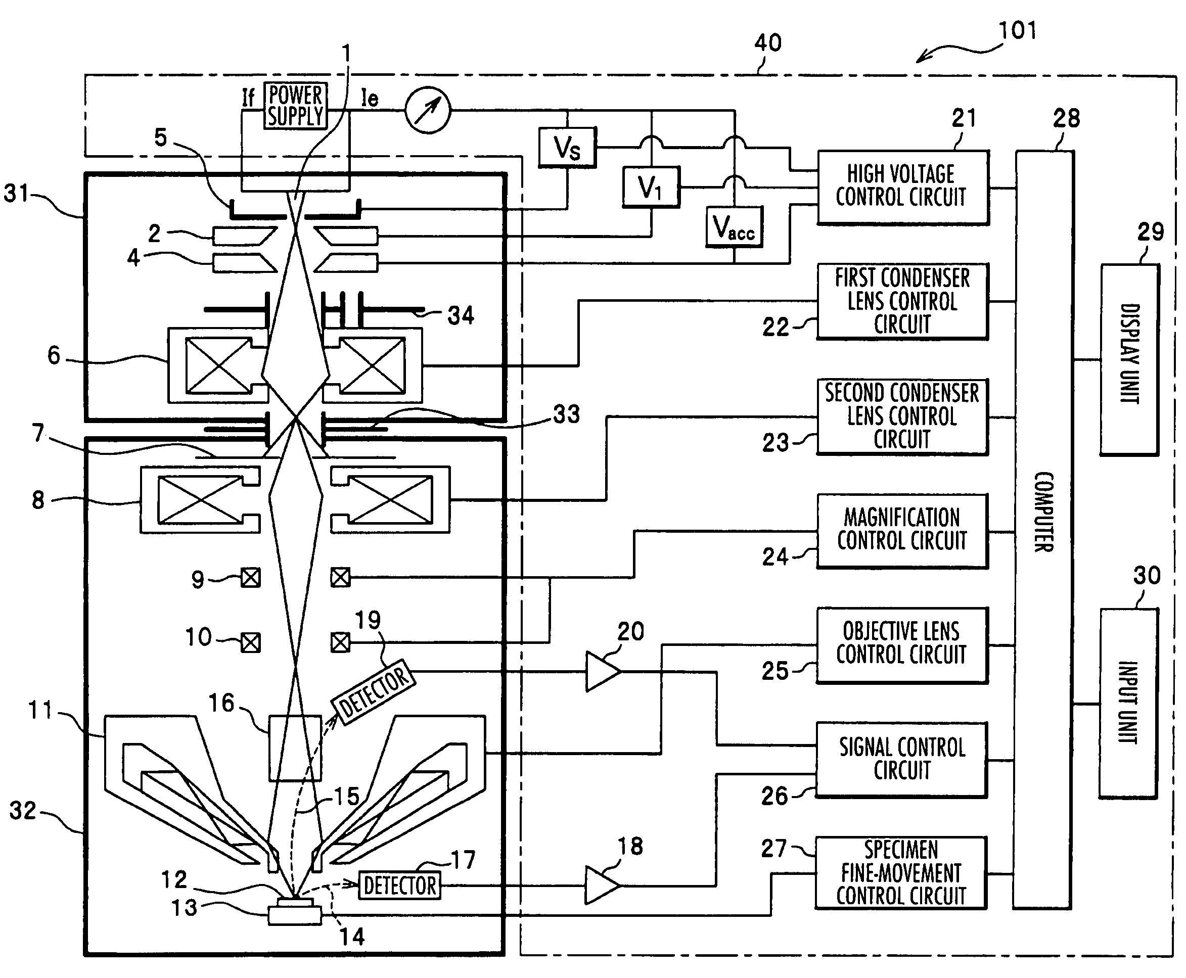
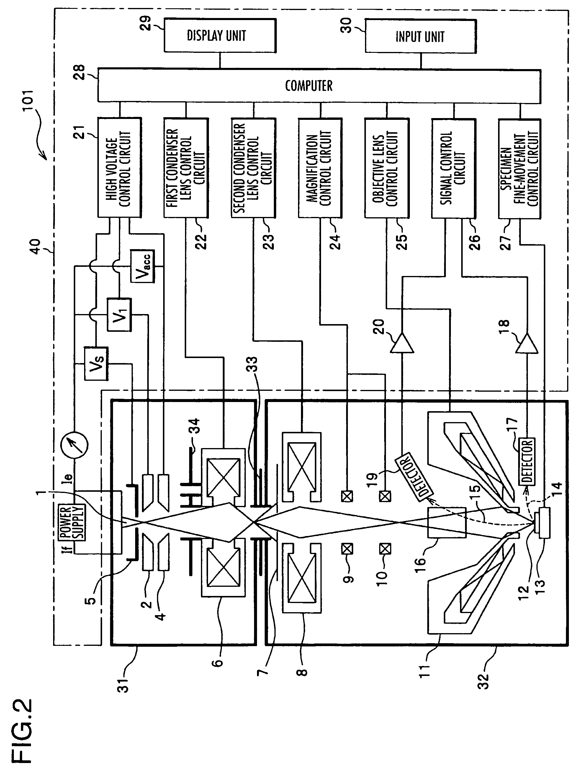
[0048]FIG. 2 is a block diagram of an arrangement of an electron beam device 101 in accordance with the present invention. Explanation will be made in connection with a case where the electron beam device 101 is a scanning electron microscope having a Schottky emission electron gun mounted therein. However, other types of the electron beam device and the electron gun may be employed. For example, the electron beam device may be a transmission electron microscope (TEM), a scanning electron microscope (SEM), or a scanning transmission electron microscope (STEM).

[0049]The electron gun may be, for example, a Schottky-type electron gun, a field-emission electron gun (FEG), a thermal (thermally assisted) field-emission electron gun, a thermionic-emission electron gun, or a cold (cathode) field-emission electron gun.

[0050]The electron beam device 101 includes an electron gun section 31 having an internal space kept at an ultrahigh vacuum level for generating a primary electron beam 3, a mi...

second embodiment

[0078]FIG. 6 is a block diagram of an arrangement of an electron beam device 102 in accordance with the present invention.

[0079]The electron beam device 102 may have an arrangement similar to that of the electron beam device 101 of the first embodiment, except that the device 102 includes an aperture diameter reading mechanism 35 provided to the diaphragm mechanism 34. The aperture diameter reading mechanism 35 has a function of reading a diaphragm aperture diameter selected in the diaphragm mechanism 34 or diaphragm information about a set number for identifying the selected diaphragm or the like. The aperture diameter reading mechanism 35 transmits the read diaphragm information to the computer 28 connected thereto. And the computer 28 selects a suitable probe current set mode according to the diaphragm aperture diameter or the set number set in the diaphragm mechanism 34. In this way, the current of the first condenser lens 6 is set by the first condenser lens control circuit 22 ...

third embodiment

[0081]FIG. 7 is a block diagram of an arrangement of an electron beam device 103 in accordance with the present invention.

[0082]The electron beam device 103 of the third embodiment may have an arrangement similar to that of the electron beam device 101 of the first embodiment, except that the device 103 includes a drive mechanism 36 mechanically or electrically connected to the diaphragm mechanism 34 and a drive mechanism control circuit 37 connected to the drive mechanism 36 and controlled by the computer 28.

[0083]When the operator changes the probe current set mode, this causes the fact of the mode change to be transmitted to the computer 28. And the drive mechanism 36 is actuated under control of the drive mechanism control circuit 37 and the diaphragm aperture diameter is automatically switched, so that the aperture diameter of the diaphragm mechanism 34 is suitably set for a probe current mode after changed.

[0084]In the electron beam device 103, even when the probe current mode...


PUM

PropertyMeasurementUnit
diametersaaaaaaaaaa
diametersaaaaaaaaaa
diameteraaaaaaaaaa

Abstract

An electron beam device includes an electron gun section having an internal space kept at an ultrahigh vacuum level for generating a primary electron beam, a mirror section having an internal space kept at a vacuum level lower than that of the electron gun section for scanning a specimen with an electron probe of the primary electron beam generated in the electron gun section and focused on the specimen, a differential exhaust diaphragm for providing communication in internal space between the electron gun section and the mirror section and passing the primary electron beam, and a control section for controlling respective constituent elements in the electron beam device. A diaphragm mechanism having a plurality of different diaphragm aperture diameters is provided between a second anode and a first condenser lens.

Description

BACKGROUND OF THE INVENTION[0001]The present invention relates to electron beam devices and more particularly, to an electron beam device which can suppress the contamination of a differential exhaust diaphragm regardless of the value of a probe current.[0002]In an electron beam device represented by a typical scanning electron microscope, various sorts of observation condition parameters are set according to a specimen or observation conditions, and a user observes the enlarged image of the specimen. The observation condition parameters include, for example, acceleration voltage, the emission current of an electron gun, condenser lens conditions, working distance (a distance between an objective lens and a specimen), conditions of a system for detecting a signal for specimen observation, and objective diaphragm aperture diameter.[0003]Other electron beam devices are used to analyze a very small region on a specimen by combining with various types of analysis devices. The analyzing ...

Claims


Application Information

Patent Timeline
Patent Type & Authority Patents(United States)
IPC IPC(8): G01N23/00
CPCH01J37/09H01J37/265H01J37/28H01J2237/0458
Inventor ICHIMURA, TAKASHIOGASHIWA, TAKESHIAGEMURA, TOSHIHIDEAOKI, KENJI
Owner HITACHI HIGH-TECH CORP
Why Eureka
Try Eureka