Vehicle air-suspension system and method of operation

a suspension system and vehicle technology, applied in the direction of rigid suspensions, vehicle components, resilient suspensions, etc., can solve the problems of unfavorable air suspension operation, acoustically perceptible drop in operating rpm, and the overdimensioned delivery capacity of compressed air delivery devices. achieve the effect of effective compressed air delivery capacity, increase in manufacturing costs, and optimization of manufacturing costs

Active Publication Date: 2009-06-30
WABCO GMBH
View PDF32 Cites 25 Cited by
  • Summary
  • Abstract
  • Description
  • Claims
  • Application Information

AI Technical Summary

Benefits of technology

[0010]An advantage of the present invention is that adaptation of the effective delivery capacity of the compressed-air delivery device takes place as a function of the procedure selected for filling the air-suspension bellows.
[0011]From the art of compressed-air-braked vehicles, for example, it is known that the delivery capacity of compressed-air delivery devices can be adapted by equipping the compressor with a pressure regulator or with governor control on the pressure-outlet side. The latter causes the compressor to cycle off and on. Another known technique for total delivery capacity adaptation is to design the dead space or clearance volume of the compressed-air delivery device with variable size, for example, by providing an additional dead space capable of being connected. Further options for adapting the delivery capacity are known from the book entitled “Das Druckluft-Kompendium” [The Compressed-Air Compendium], published in 1997 by VML-Verlag (ISBN 3-89646-003-X).
[0012]The known options for adaptation of the delivery capacity are associated with additional equipment complexity and thus additional costs. For air-suspension systems for passenger cars in particular, the compressed-air delivery device is provided mainly for supplying the air-suspension system. In contrast to compressed-air-powered brake systems of trucks, for example, it is not designed to supply compressed air additionally or even mainly to consuming units other than the air-suspension system. Because of the limited operational need, therefore, the compressed-air delivery devices preferably used in passenger cars are greatly optimized in terms of manufacturing costs. Thus additional equipment complexity for adaptation of the delivery capacity is not desired.
[0013]An advantage of the invention is that the additional capability for adaptation of the effective delivery capacity can be achieved by expanding an electronic control unit running a control program by appropriate control steps, or in other words program steps in a software program, in a manner matched to the accessories and design of the air-suspension system. In this way additional equipment complexity can be completely avoided if necessary.
[0014]Yet another advantage of the present invention is that the operating noise unavoidably made by the compressed-air delivery device can be made more uniform by adaptation of the effective delivery capacity. Thereby this noise can be made less noticeable to a user of the air-suspension system, such as a vehicle operator. In addition, overheating and associated overloading of the compressed-air delivery device can be avoided by simple means.
[0015]Still other objects and advantages of the present invention will in part be obvious and will in part be apparent from the specification.

Problems solved by technology

On the other hand, if only a subset of the air-suspension bellows—two, for example—will be filled with compressed air, for example, to compensate for a leaning condition of the vehicle chassis, it may occur that the delivery capacity of the compressed-air delivery device is overdimensioned for such a situation.
This can lead to an undesired large pressure rise on the pressure-outlet side of the compressed-air delivery device, since the compressed-air quantity discharged by the compressed-air delivery device cannot flow rapidly enough into the air-suspension bellows.
In an electrically driven compressed-air delivery device, such an undesired large pressure rise can lead to an acoustically perceptible drop in operating rpm.
In addition, the electrical current drawn by the compressed-air delivery device's motor can increase to an undesirably high level, in turn causing a safety circuit to trip in the vehicle, among other effects.
Finally, an excessive pressure can also lead to damage or increased wear of parts of the compressed-air system.

Method used


Image

  • Vehicle air-suspension system and method of operation
  • Vehicle air-suspension system and method of operation
  • Vehicle air-suspension system and method of operation

Examples


Embodiment Construction

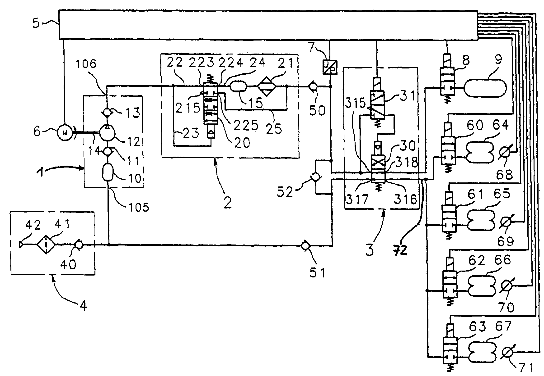
[0028]The task of an air-suspension system for a vehicle is to adjust and control, via leveling means, the level height of the vehicle chassis relative to the vehicle axles and thus indirectly relative to the roadway. For this purpose such a leveling means is preferably disposed on each wheel of a vehicle, and air-suspension bellows are preferably used as leveling means. By filling or venting the individual air-suspension bellows, any desired level heights of the vehicle chassis can be adjusted within an adjustment range provided for the purpose. Such air-suspension systems are preferably operated with compressed air as the pressurized medium.

[0029]The term “open system” when used in connection with air-suspension systems, means a system in which the compressed air is sucked in as necessary from the surroundings, or in other words from the atmosphere, and pumped into the air-suspension bellows or into a compressed-air accumulator, or in other words a reservoir tank. The compressed-a...


PUM


Abstract

A vehicle air-suspension system, especially an air-suspension system designed as a partly closed system, and a method for operating the system are provided. The air-suspension system includes at least one compressed-air delivery device, a plurality of air-suspension bellows and valves constructed and arranged for control of the filling of one, several or all air-suspension bellows with compressed air discharged by the compressed-air delivery device. The method avoids an undesirably large pressure rise on the pressure-outlet side of the compressed-air delivery device as the effective delivery capacity of the compressed-air delivery device is automatically controlled as a function of the state defined by the arrangement of the valves.

Description

BACKGROUND OF THE INVENTION[0001]The present invention relates to an air-suspension system for a vehicle and a method for the operation of said air-suspension system.[0002]Vehicle air-suspension systems as well as methods for their operation are known, for example, from DE 100 55 108 A1.[0003]An air-suspension system for a vehicle is typically provided with a plurality of air-suspension bellows in the region of the respective wheel suspension of the individual wheels of the vehicle. The air-suspension bellows can be filled with compressed air via a compressed-air delivery device such as a compressor. During practical operation of such an air-suspension system, the level changes at the individual wheel suspensions of the vehicle and thus the processes of filling of the air-suspension bellows must be completed as rapidly as possible. For this reason, it is advisable to design the compressed-air delivery device with sufficient delivery capacity to meet the maximum delivery demand that ...

Claims


Application Information

Patent Timeline
Patent Type & Authority Patents(United States)
IPC IPC(8): B60G11/26B60G1/00B60G11/27B60G17/015B60G17/04B60G17/052
CPCB60G17/0155B60G17/04B60G17/0523B60G2500/2014
Inventor MATERN, DANIELMEIER, JORGBODET, MARC
Owner WABCO GMBH
Why Eureka
Try Eureka