Magnetohydrodynamic energy conversion device using a heat exchanger

Inactive Publication Date: 2009-06-30
KAY THOMAS P
View PDF6 Cites 18 Cited by
  • Summary
  • Abstract
  • Description
  • Claims
  • Application Information

AI Technical Summary

Benefits of technology

[0007]Typically, an effort is made to use a heat source capable of elevating the temperature of the working fluid as high as possible, since higher temperatures result in greater ionization of the working material and hence increased electrical output. However, i

Problems solved by technology

Typically, an effort is made to use a heat source capable of elevating the temperature of the working fluid as high as poss

Method used


Image

  • Magnetohydrodynamic energy conversion device using a heat exchanger
  • Magnetohydrodynamic energy conversion device using a heat exchanger
  • Magnetohydrodynamic energy conversion device using a heat exchanger

Examples


Embodiment Construction

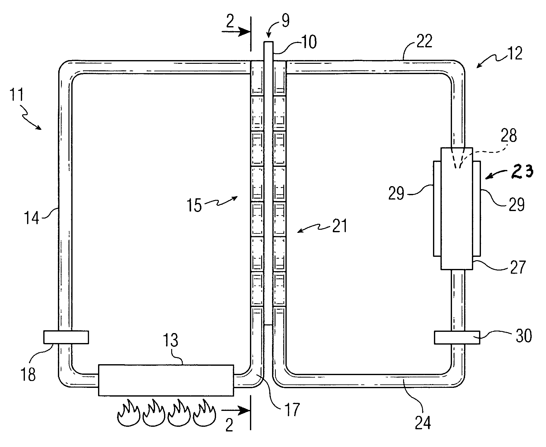
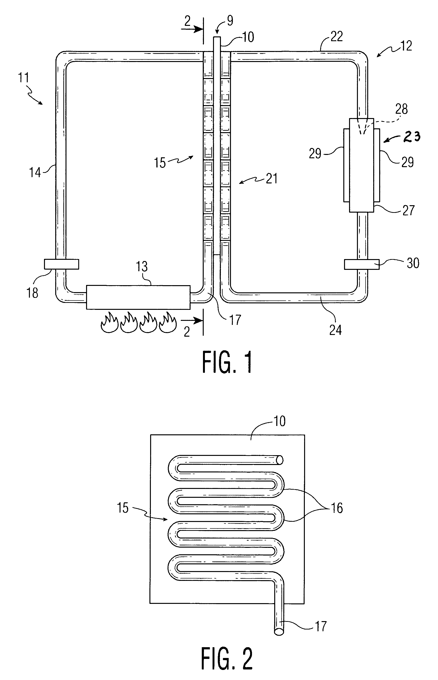
[0013]Referring to FIGS. 1 and 2, an installation according to this invention presents a heat exchanger 9 including a flat plate 10 made of a material having good thermal conductivity, such as copper. At one side of plate 10 is a circuit 11 for providing heat energy. At the other side of plate 10 is an MHD circuit 12 including a conventional MHD electrode system.

[0014]Circuit 11 is a closed circuit filled with an appropriate liquid, such as oil or water. The circuit includes a heat source 13 for elevating the temperature of the liquid in the circuit. If the liquid is heated to boiling, steam will flow through the circuit. The heat source may be a fuel burner for burning a fuel such as oil, coal, or natural gas. Alternatively, heat source 13 may be derived from a geothermal source or may involve a solar collector of the type including an array of liquid-containing tubes. The heat source could be heat produced by any industrial process, including heat generated by a conventional power...


PUM


Abstract

An energy conversion device for generating electricity includes a heat exchanger adapted to receive heat from a heat source. A closed magnetohydrodynamic (MHD) circuit includes a section for extracting heat from a heat exchanger so as to raise the temperature of the flowable electrically conductive material within the MHD circuit. The heat exchanger includes a heat-conductive support adapted to be heated, and a heat-extracting section of the MHD circuit extracts heat from the support. The support may be a metal plate having a sinuous pipe arrangement in heat-conductive contact against each face, one of these pipe arrangements being part of a circuit for heating the plate and the other pipe arrangement being part of the MHD circuit. The heat source may be combustion of a fuel, solar, geothermal, chemical reaction, or waste heat in the form of a hot gas. The heat conductive support may be a metal tube heated, usually by a hot gas, in which case the heat-extracting section of the MHD circuit includes a helical pipe surrounding the tube. The heat-providing means may include a lens arrangement for concentrating solar radiation on one face of the heat exchanger plate.

Description

BACKGROUND OF THE INVENTION[0001]This invention relates to magnetohydrodynamic (MHD) energy conversion devices capable of converting heat directly into electrical energy.[0002]As is well known, in an MHD conversion device, an electrically-conductive ionized gas flows through a magnetic field perpendicular to the direction of gas flow. This action generates an electric current in the gas, which is tapped by electrodes located in the magnetic field and in contact with the moving gas. One way of obtaining the electrically-conductive gas is to heat an ionizable working substance, such as cesium to produce the working fluid. Examples of MHD devices used to convert solar and laser energy into electricity are illustrated and described in U.S. Pat. Nos. 4,191,901 and 4,275,318.[0003]A problem presented by MHD energy conversion devices of the prior art is that they tend to have limited versatility in the heat sources they can use for the energy conversion, and in the locations where they can...

Claims


Application Information

Patent Timeline
IPC IPC(8): H02K44/08
CPCH02K44/085F28D15/00F24S23/30Y02E10/40
Inventor KAY, THOMAS P.
Owner KAY THOMAS P
Why Eureka
Try Eureka