
Synchronous machine control apparatus

a control apparatus and synchronous machine technology, applied in the direction of electric generator control, dynamo-electric converter control, dynamo-electric gear control, etc., can solve the problems of difficult to control the armature voltage to match a desired value, and difficult to control the motor torque with high precision by conventional control methods

Inactive Publication Date: 2009-06-30
MITSUBISHI ELECTRIC CORP
View PDF11 Cites 30 Cited by
  • Summary
  • Abstract
  • Description
  • Claims
  • Application Information

AI Technical Summary

Benefits of technology

[0028]Returning to FIG. 3, the optimum flux command calculator 17 stores the aforementioned relationship between the δ-axis current iδ and the magnitude |Φ| of the magnetic flux in the form of an equation or a data table and outputs an optimum flux command Φ** which is the magnitude of optimum magnetic flux in accordance with the input δ-axis current command iδ*. While the δ-axis current command iδ* and the optimum flux command Φ** are so correlated as to maximize an output torque in the above explanation, the optimum flux command Φ** may aim at maximum efficiency, for instance, depending on the purpose of operation. Generally, it is possible to obtain operational characteristics suited to the purpose of operation if the δ-axis current command iδ* and the optimum flux command Φ** are correlated such that desired performance is maximized.
[0104]Also, the flux command generator calculates a relationship between a torque current and the interlinked armature flux through a learning process such that the flux command generator outputs the flux command based on the relationship between the torque current and the interlinked armature flux, wherein the torque current is determined under conditions where the magnitude of the armature current or input power is minimized with the torque command set to a fixed value. It is therefore possible to realize useful synchronous machine control which can minimize the magnitude of the armature current or input power under given conditions even when operational characteristics of the synchronous machine are not known in advance or characteristics obtained by mathematical analysis differ from actual machine characteristics.

Problems solved by technology

On the other hand, while synchronous machines which utilize reluctance torque produced by saliency of the rotor are increasingly used in recent years, it is known that the magnitude of the armature current vector is not proportional to a torque produced by these motors and, thus, it is difficult to control the motor torque with high precision by conventional control methods.
It has therefore been difficult to control the armature voltage to match a desired value under conditions of varying output torque by the conventional control methods.

Method used


Image

  • Synchronous machine control apparatus
  • Synchronous machine control apparatus
  • Synchronous machine control apparatus

Examples


first embodiment

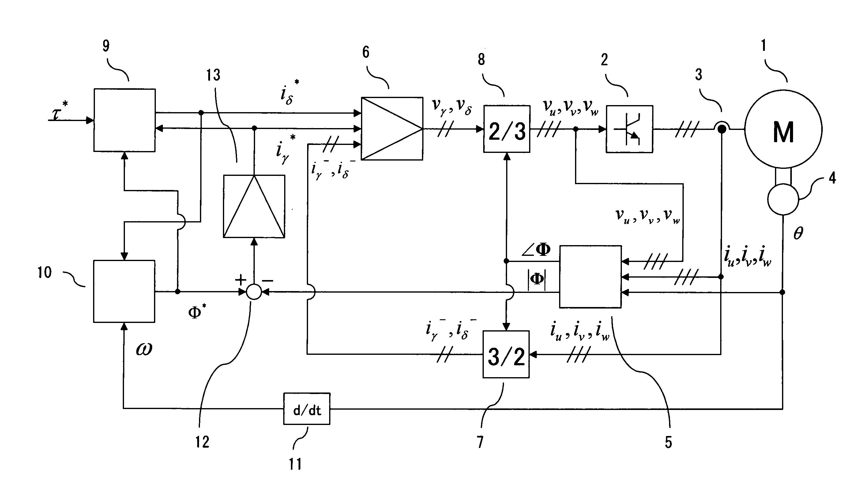
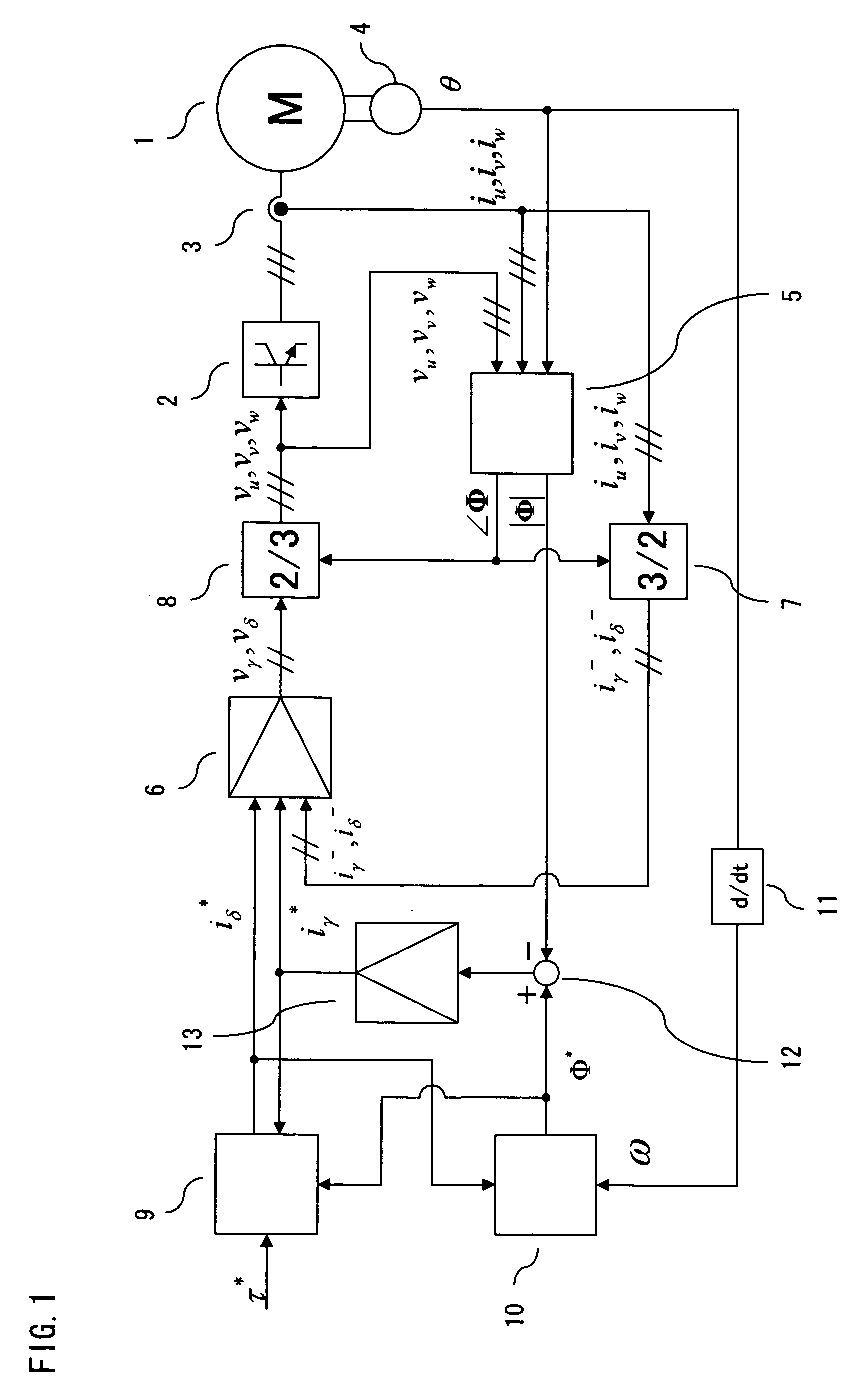
[0011]FIG. 1 is a configuration diagram showing a synchronous machine control apparatus according to a first embodiment of the present invention. A synchronous machine 1 is driven with armature windings thereof connected to a three-phase drive circuit 2 which works as a power conversion unit. A current flowing through each armature winding is detected by a current sensor 3. Also, rotor phase (electrical angle) θ of the synchronous machine 1 is detected by a rotor position sensor 4.

[0012]As will be later discussed with reference to FIGS. 6 and 7, a flux calculator 5 calculates the magnitude |Φ| and phase ∠Φ of interlinked armature flux from three-phase armature current feedback values iu, iv, iw and three-phase voltage commands vu*, vv*, vw* (which are written in simplified forms as vu, vv, vw in the Figure), for example.

[0013]Since armature currents are controlled on two axes, that is, the direction (γ-axis) of the phase ∠Φ of the interlinked armature flux and a direction (δ-axis) p...

second embodiment

[0048]FIG. 8 is a configuration diagram showing a synchronous machine control apparatus according to a second embodiment of the present invention. This embodiment shows a configuration in which a direct current (DC) source voltage of the three-phase drive circuit 2 is made variable. The numerals 1-9 and 11-13 designate elements which are the same as those of the first embodiment.

[0049]Advantages produced by making the DC source voltage of the three-phase drive circuit 2 variable are explained below.

[0050]Generally, a DC source voltage of an inverter which works as a power conversion unit is determined by a power supply (a battery or an alternating current power supply) that is used. On the other hand, a permanent magnet motor produces an induced voltage which is generally proportional to turning speed. Thus, in order to increase the turning speed while limiting motor voltages to a level equal to or lower than an upper limit of the inverter, it is necessary to run the motor by field-...

third embodiment

[0061]FIG. 10 shows a third embodiment of the present invention.

[0062]In the torque current command generator 9 of the aforementioned first embodiment, the torque command τ* given from a preceding stage has a value which can be used as it is.

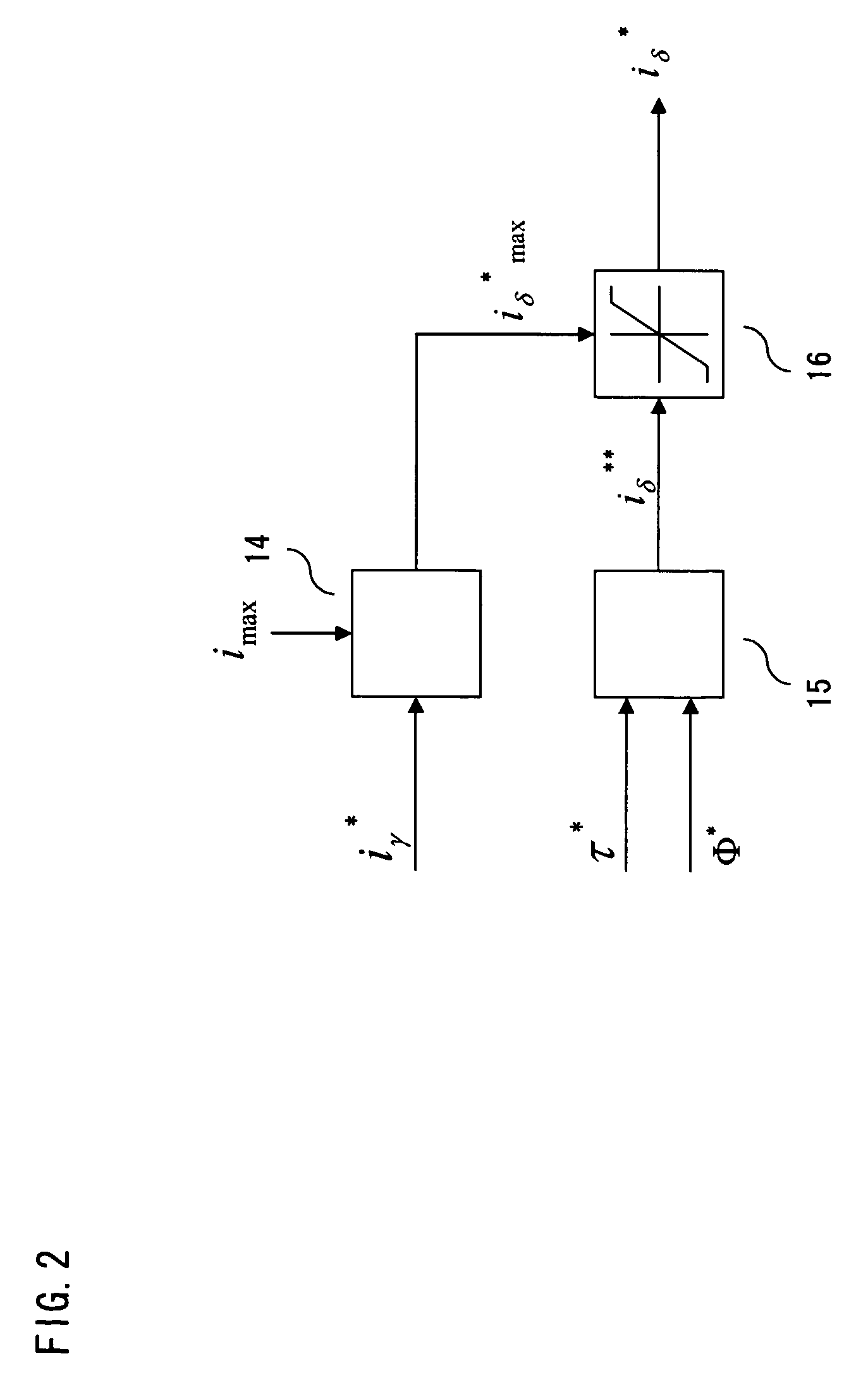
[0063]If the inductance of the synchronous machine 1 is large, however, there may arise a case where it is necessary to limit the torque command τ* for matching the interlinked armature flux Φ with the flux command Φ*. FIG. 10 is a diagram showing an internal configuration of a torque current command generator 9 employed when such torque limitations are necessary. Referring to this Figure, a torque limit generator 32 outputs a maximum torque τ*max which can be generated with magnetic flux specified by the flux command Φ* with reference to the flux command Φ*, and a limiter 33 outputs a limited torque command τ* by limiting the original torque command τ* to the maximum torque τ*max. A torque current limit generator 14, a torque current calculator...


PUM


Abstract

A synchronous machine control apparatus which can produce a torque level as close as possible to a desired torque command level while considering limitations on an output current of a power conversion unit. A synchronous machine control apparatus includes a torque current command generator including a torque current calculator for calculating a torque current command iδ** from a torque command τ* and a flux command φ*, a torque current limit generator for generating a maximum torque current command value iδ* max that can be generated based on a magnetizing current command iγ* and a current limit value imax, and a limiter for imposing limitations on iδ** based on iδ* max, a flux command generator for calculating the flux command φ* based on iδ* fed from the torque current command generator, a flux calculator for calculating an interlinked armature flux feedback value |Φ| based on an armature current feedback value, and a flux controller for generating the magnetizing current command iγ* such that φ* and |Φ| coincide with each other and delivering iγ* to the torque current command generator.

Description

TECHNICAL FIELD[0001]The present invention relates to a control apparatus for a synchronous machine, such as a permanent magnet motor or a reluctance motor.BACKGROUND ART[0002]Conventionally, a synchronous machine, such as a permanent magnet motor or a reluctance motor, is controlled such that an armature current vector is oriented in a fixed phase direction with respect to a rotor. For example, a conventional permanent magnet motor is controlled such that an armature current vector is oriented in a direction perpendicular to an axis of magnetic flux produced by each permanent magnet of a rotor and the magnitude of the armature current vector becomes proportional to a desired torque.[0003]On the other hand, while synchronous machines which utilize reluctance torque produced by saliency of the rotor are increasingly used in recent years, it is known that the magnitude of the armature current vector is not proportional to a torque produced by these motors and, thus, it is difficult to...

Claims


Application Information

Patent Timeline
Patent Type & Authority Patents(United States)
IPC IPC(8): H02P7/00H02P21/00H02P21/06H02P21/10H02P21/22H02P23/16H02P23/22H02P25/022H02P25/026H02P25/08H02P27/04H02P27/06H02P27/08H02P29/00H02P29/40
CPCB60L11/1803B60L15/025B60L15/2045H02P21/14H02P21/0035B60L2220/14Y02T10/7283Y02T10/643Y02T10/7005B60L50/51H02P21/22Y02T10/64Y02T10/70Y02T10/72H02P21/00
Inventor SATAKE, AKIRAHAISHI, ATSUO
Owner MITSUBISHI ELECTRIC CORP
Learn More