Optical disc playback apparatus

a playback apparatus and optical disc technology, applied in the field of optical disc playback apparatus, can solve the problems of degrading the accuracy of offset correction, the inability to accurately detect a digital binary signal and a jitter, and the inability to control performance, etc., to achieve high accuracy, high playback performance, and high accuracy

Inactive Publication Date: 2009-07-07
PANASONIC HEALTHCARE HLDG CO LTD
View PDF2 Cites 30 Cited by
  • Summary
  • Abstract
  • Description
  • Claims
  • Application Information

AI Technical Summary

Benefits of technology

[0021]The optical disc playback apparatus according to the present invention is provided with the first offset correction circuit for performing phase sync control corresponding to high-speed control based on the premise of linear interpolation, and the second offset correction circuit for performing offset correction with high accuracy based on the premise of Nyquist interpolation. Thereby, the first offset correction and the phase sync control can be carried out in response to each other, against defects or rapid offset fluctuations. Further, in both of the level determination method and the PRML signal processing method, offset components in the amplitude direction of signals used for the respective methods can be accurately reduced by the second offset correction. Therefore, sufficient playback performance can be realized even when an asymmetry, which exists in the playback RF signal depending on the recording quality of recorded digital data, is large.
[0022]Furthermore, in the optical disc playback apparatus according to the present invention, since detection of jitter which serves as an indicator of the playback signal quality can be carried out with high accuracy, it is possible to accurately perform adjustment of the cutoff frequency and boost learning of an analog equalizer to improve the jitter of the playback RF signal, and adjustment of the best point for balance learning in focus servo relating to the performance of the playback RF signal, resulting in significant increase in the playback signal quality even during high-speed playback.

Problems solved by technology

In the conventional construction, however, when an asymmetry, i.e., an up-to-down asymmetric distortion which occurs dependently of the quality of the recorded digital data in the playback RF signal, is large, a calculation error due to the asymmetry occurs in the method of correcting an offset component in the amplitude direction by restoring data missing in the time direction by linear interpolation, thereby degrading offset correction accuracy.
Further, in the case where the offset correction accuracy is improved by data interpolation using the Nyquist filter when the offset component is corrected, since the Nyquist interpolation processing causes an increase in the length of the feedback control loop, the control performance is degraded when high-speed feedback control is required against defects or rapid offset fluctuations.
However, when asymmetry is large, detection of a digital binary signal and detection of jitter cannot be accurately carried out.

Method used


Image

  • Optical disc playback apparatus
  • Optical disc playback apparatus
  • Optical disc playback apparatus

Examples


embodiment 1

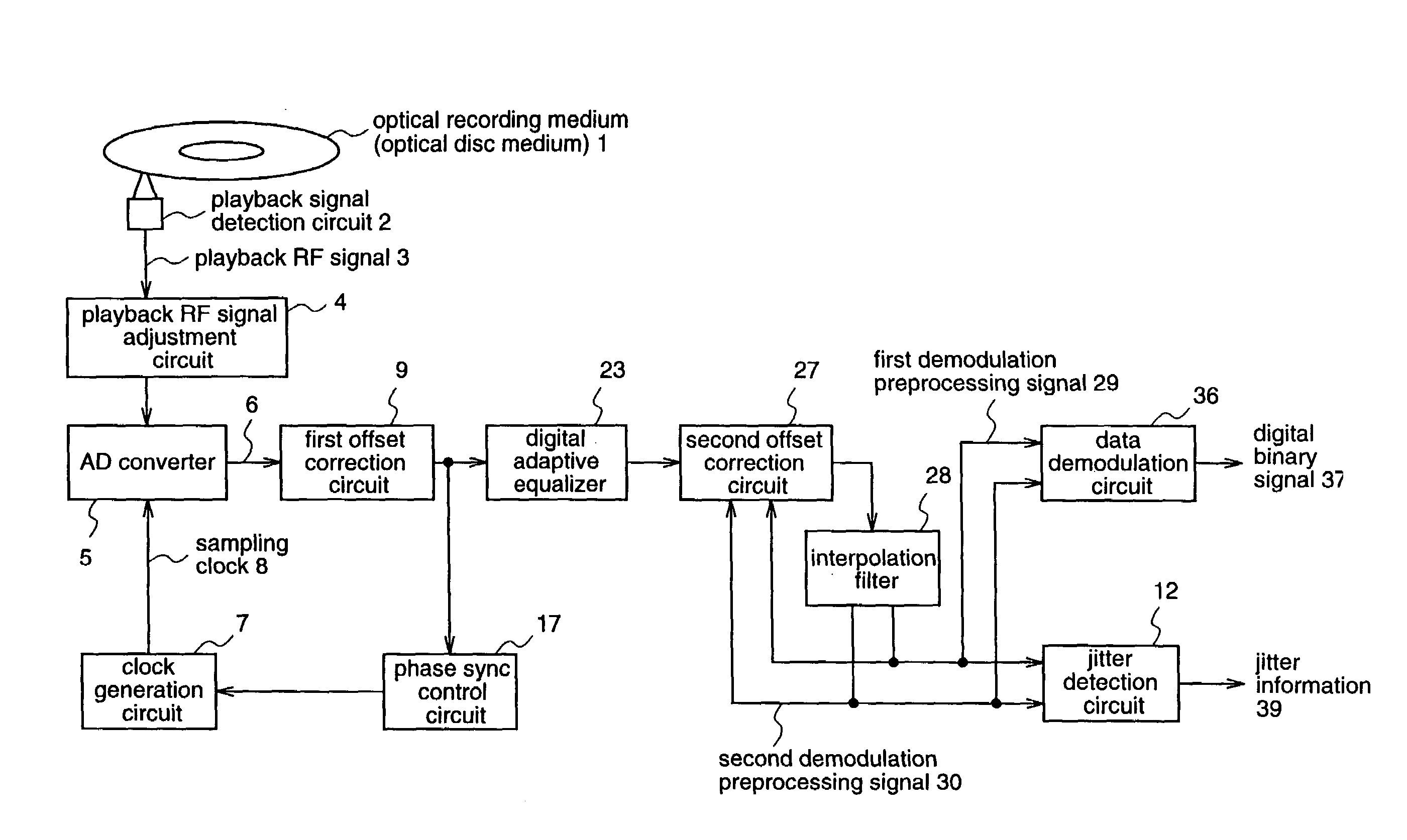
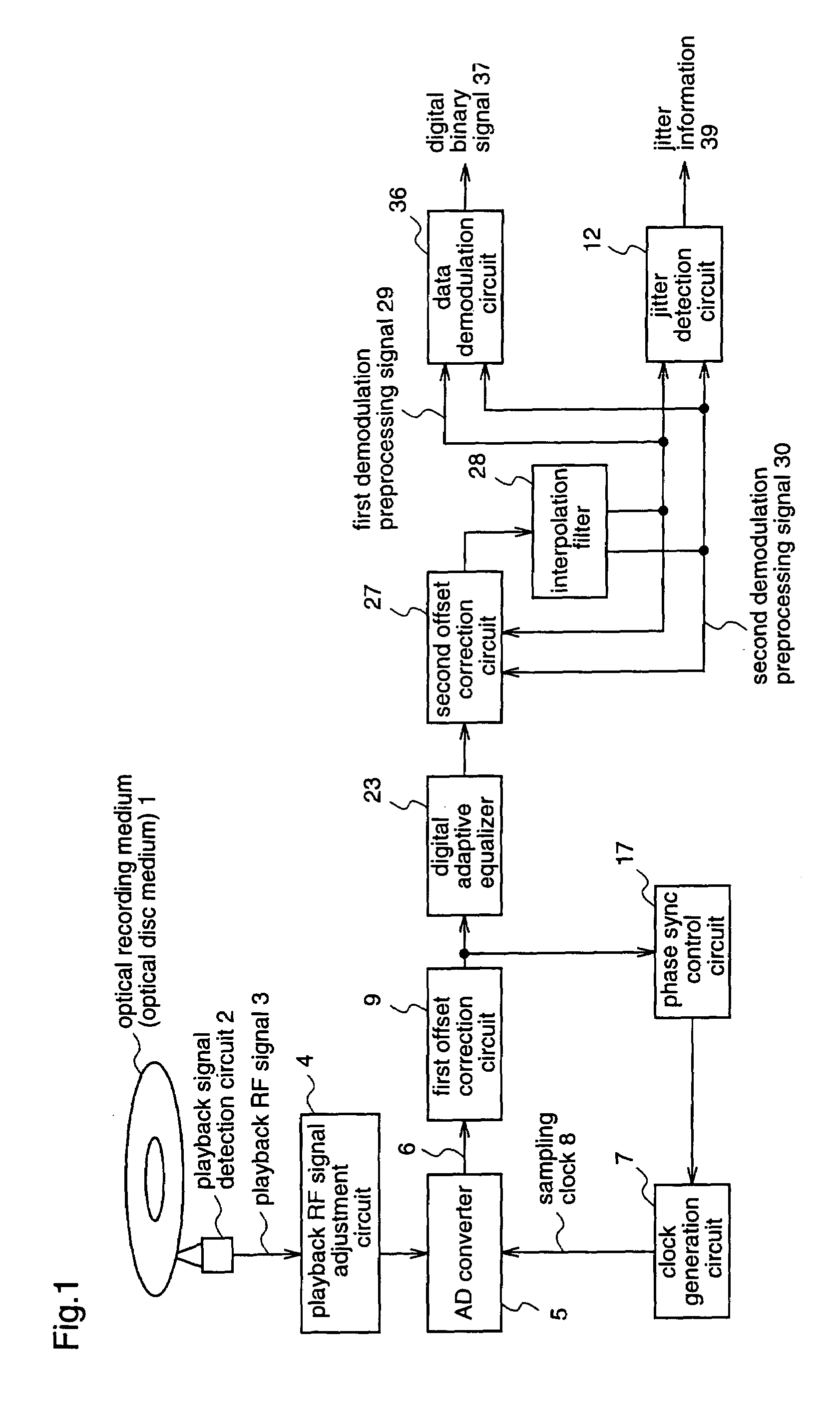
[0048]FIG. 1 is a block diagram illustrating the construction of an optical disc playback apparatus according to a first embodiment of the present invention.

[0049]This first embodiment corresponds to claims 1 to 5 of the present invention. When digitizing a playback RF signal reproduced from an optical disc medium to demodulate a digital binary signal, the playback RF signal is converted into a digital signal synchronized with a sampling clock having a cycle twice as long as a channel bit cycle, and thereafter, phase sync control, adaptive equalization, jitter detection and the like are effectively functioned by employing a first offset correction circuit adaptable to high-speed control and a second offset correction circuit adaptable to low-speed control and sensitive to offset correction accuracy, whereby low power consumption is realized, and high-performance playback can be realized even when an asymmetry existing in the playback RF signal is large.

[0050]With reference to FIG. 1...

embodiment 2

[0082]FIG. 10 is a block diagram illustrating the construction of an optical disc playback apparatus according to a second embodiment of the present invention.

[0083]The second embodiment corresponds to claims 6 and 7 of the present invention. This second embodiment is different from the first embodiment in that the second embodiment is provided with a circuit for generating a sampling phase switching flag for selecting either phase sync control using the same phase as used in the first embodiment or phase sync control using a phase that is 180 degrees different from the phase of the first embodiment, when performing phase sync control in terms of a channel bit clock; and a means for changing the modes of the first offset correction circuit, the phase sync control circuit, the digital adaptive equalizer, the second offset correction circuit, and the data demodulation circuit to the sampling mode according to the PRML signal processing method, on the basis of the sampling phase switch...


PUM

PropertyMeasurementUnit
phase erroraaaaaaaaaa
timeaaaaaaaaaa
speedaaaaaaaaaa

Abstract

After a playback RF signal 3 detected from an optical disc medium 1 is waveform-shaped, it is converted into a digital RF signal 6 with a sampling clock 8 having a cycle twice as long as a channel clock. Thereafter, a first offset correction circuit 9 corrects an offset fluctuation in a high frequency band, and a digital adaptive equalizer 23 performs adaptive equalization, and then a second offset correction circuit 27 corrects an offset component that remains after the offset correction by the first offset correction circuit 9, thereby demodulating a digital binary signal 37. Therefore, even when high-speed playback is carried out and an asymmetry depending on the recording quality is large, a reduction in power consumption can be realized while maintaining high-performance playback. Consequently, it is possible to provide an optical disc playback apparatus which can realize sufficient playback performance at low power consumption.

Description

FIELD OF THE INVENTION[0001]The present invention relates to an optical disc playback apparatus for reproducing digital data from an optical recording medium. More specifically, the invention relates to a read channel technique for demodulating a digital binary signal from a playback RF signal.BACKGROUND OF THE INVENTION[0002]As a method for recording digital data on optical disk media, there has commonly been employed a method of uniformizing the recording density on a recording medium by making the linear velocity constant, as seen in a compact disk (hereinafter referred to as a CD), a DVD (Digital Versatile Disk), and a DVD-RAM (Digital Versatile Disk-Random Access Memory). When reproducing a digital binary signal from a playback RF (Radio Frequency) signal which is digitally recorded by performing mark width modulation so as to make the linear recording density constant, a digital read channel method employing a PRML (Partial Response Maximum Likelihood) signal processing techni...

Claims


Application Information

Patent Timeline
Patent Type & Authority Patents(United States)
IPC IPC(8): G11B7/00G11B7/005G11B20/10G11B20/18H04L25/02
CPCG11B20/10037G11B20/10046G11B20/10055G11B20/10083G11B20/10101G11B20/10166G11B20/10203G11B20/10212G11B20/10222G11B20/10111G11B2220/2537G11B20/1876G11B20/10
Inventor OGURA, YOUICHIKONISHI, SHINICHI
Owner PANASONIC HEALTHCARE HLDG CO LTD
Why Eureka
Try Eureka