Advance signaling for multi-stage tranceivers

a multi-stage, advanced technology, applied in the direction of power management, transmission monitoring, receiver monitoring, etc., can solve the problems of high-speed unmodulated data passing back and forth between the computer and the subscriber unit, the signal may be passed between physically distinct components and the power control loop performance of the subscriber unit may be improved. , to achieve the effect of improving the power control loop performance of the subscriber uni

Inactive Publication Date: 2009-07-07
CISCO TECH INC
View PDF12 Cites 10 Cited by
  • Summary
  • Abstract
  • Description
  • Claims
  • Application Information

AI Technical Summary

Benefits of technology

[0010]Systems and methods for advanced signaling between stages of transmitters and / or receivers in a digital communication system are provided by virtue of one embodiment of the present invention. One aspect of the invention provides for one or more intermediate frequency signals and one or more control signals on the same cable. Another aspect of the invention provides systems and methods for calibrating head end receiver gain to improve subscriber unit power control loop performance.

Problems solved by technology

One problem arises in passing signals between physically distinct components of the subscriber unit.
If the subscriber unit were to be integrated within one physical package inside the building in proximity to the computer, a problem arises in that RF signals will attenuated by the cable between the indoor subscriber unit housing and the outdoor antenna.
If the subscriber unit is a single physical package outside the house at the antenna location, another problem arises in that high speed unmodulated data passing back and forth between the computer and subscriber unit may be corrupted over the relatively long distance between the subscriber unit and computer.
Yet it is impractical to pass multiple cables between the indoor unit and outdoor unit because this would greatly complicate installation and maintenance.
Another interstage signaling problem arises at the head end.
If this transmission power level is too low, the subscriber unit signal received at the head end will be too weak to accurately recover the transmitted digital data.
If this transmission power level is too high, the subscriber unit signal may saturate the head end receiver or cause interference to communication links operating outside network 100.
For example, network 100 may be a single cell of a multicellular system and excessive transmission power may cause interference to other cells.
Because recovery of the transmitted data occurs after the measurement point, the variation of this signal gain and the resulting variation of subscriber unit transmission power will not affect head end receiver power, however, an increase in subscriber unit transmission power due to receiver gain changes rather than channel conditions will potentially cause interference to cells outside network 100.
However during operation it is difficult to accurately measure head end receiver gain because although the signal level at the measurement point is known, there is no easy way to measure the signal level incident at the antenna.

Method used


Image

  • Advance signaling for multi-stage tranceivers
  • Advance signaling for multi-stage tranceivers
  • Advance signaling for multi-stage tranceivers

Examples


Embodiment Construction

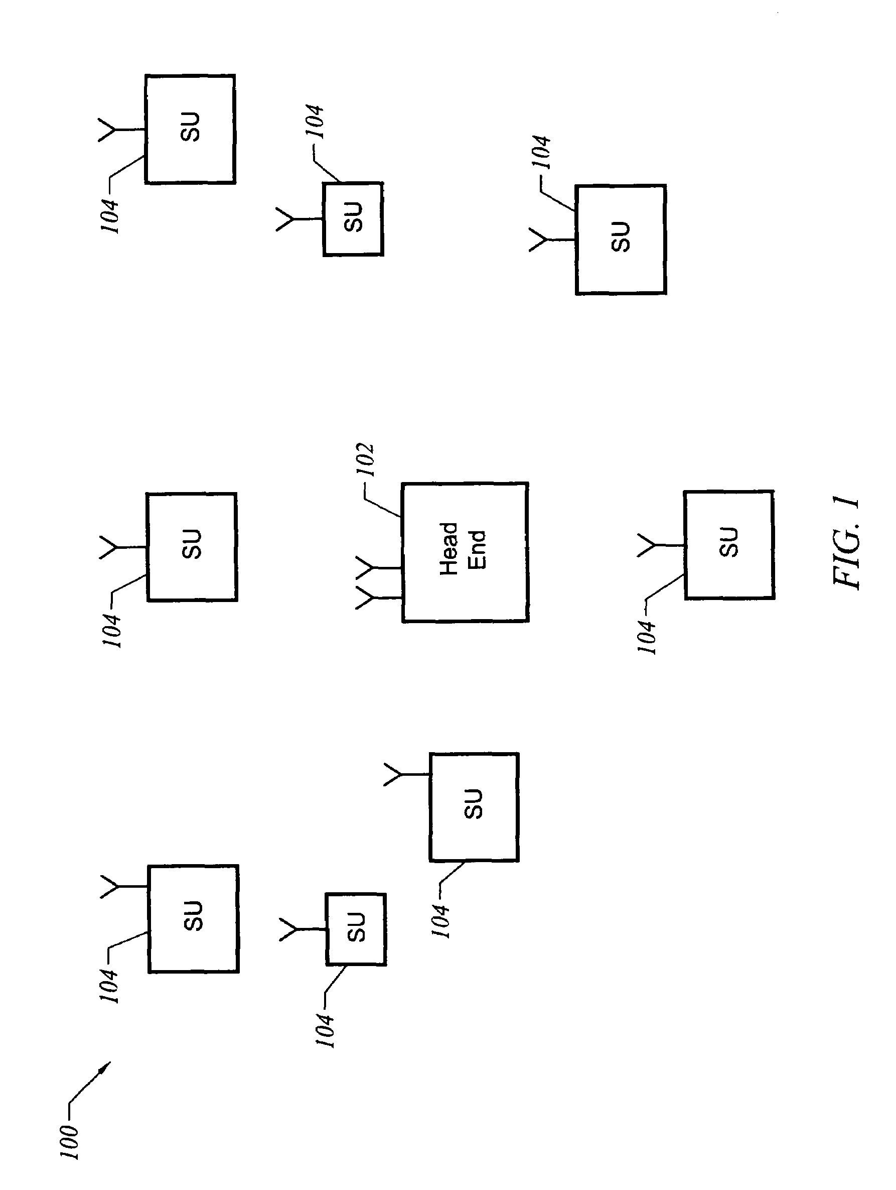
[0019]A point to multipoint communication system is one example of an application of the present invention. The present invention is, however, of course not limited to point to multipoint communication systems but also finds application in e.g., point to point or peer to peer communication systems. FIG. 1 depicts a representative point to multipoint communication system. A network 100 includes a central access point or head end 102 and multiple subscriber units 104. All communications typically is either to or from head end 102. Communication from head end 102 to one or more subscriber units 104 is herein referred to as downstream communication. Communication from any one of subscriber units 104 to head end 102 is herein referred to as upstream communication. In one embodiment, different frequencies are allocated to upstream and downstream communication. In order to coordinate communication along multiple subscriber units via a common upstream frequency, a medium access control (MAC...


PUM


Abstract

Systems and methods for advanced signaling between stages of transmitters and/or receivers in a digital communication system. One or more intermediate frequency signals and one or more control signals may share the same cable. Also, systems and methods are provided for calibrating head end receiver gain to improve subscriber unit power control loop performance.

Description

BACKGROUND OF THE INVENTION[0001]The present invention relates to digital communication systems and more particularly to digital communication systems employing multi-stage transceivers.[0002]A point to multipoint wireless communication system represents a potentially effective solution to the problem of providing broadband network connectivity to a large number of geographically distributed points. Unlike optical fiber, DSL, and cable modems, there is no need to either construct a new wired infrastructure or substantially modify a wired infrastructure that has been constructed for a different purpose. The point to multipoint system includes both a hub or a head end and numerous subscriber units associated with individual residences or businesses. For both the subscriber unit and head end, there is a transceiver including both a transmitter and a receiver. Both the transmitter and receiver incorporate various stages. Special problems arise in signaling among the stages as will be ex...

Claims


Application Information

Patent Timeline
Patent Type & Authority Patents(United States)
IPC IPC(8): H04B1/06H04B7/00
CPCH04B17/318H04B17/21H04W52/245
Inventor RAISSINIA, ALIREZATAYLOR, GREGORYRALEIGH, GREGORYPOLLACK, MICHAELJONES, IV, VINCENT K.
Owner CISCO TECH INC
Why Eureka
Try Eureka