Impact-resistant acceleration sensor

a sensor and acceleration technology, applied in the field of acceleration sensors, can solve the problems of ridges or corners of the bottom surface of the weight made of silicon chipping at a certain low frequency, excessive weight amplitude, and breakage of elastic arms, and achieve the effect of high impact resistan

Inactive Publication Date: 2009-07-21
HITACHI METALS LTD
View PDF13 Cites 9 Cited by
  • Summary
  • Abstract
  • Description
  • Claims
  • Application Information

AI Technical Summary

Benefits of technology

[0011]The present invention has been accomplished to resolve the aforementioned problems and provides an acceleration sensor, in which a protection case made of ceramic, glass or silicon is used, that has realized such a high impact-resistance that chipping of edges or corners of a weight bottom surface of an acceleration sensor element is avoided.
[0022]It is preferable that the impact buffer material used in the acceleration sensor of the present invention is a metal layer of aluminum, copper, silver, gold or an alloy containing one of them as a main component, or a resin layer of fluorocarbon-series polymer, polyolefin-series resin, rubber-series material, fluoro-elastomer, fluoro-polymer or epoxy-series resin, and has a thickness of 1.0 μm or more. The metal layer is preferably formed by sputtering, vapor-deposition or plating, and has a thickness of 10 μm or less. The resin layer formed by painting preferably has a thickness of 200 μm or less. A metal layer formed by a bonded metal foil or a resin layer formed by a bonded plastic sheet is preferably 300 μm or less in thickness. By using, for an impact buffer material, aluminum, copper, silver or gold that is used for electrodes and lead wires of acceleration sensor elements, the impact buffer material can be formed without increasing material kinds of sputtering targets.
[0024]When an excessive acceleration is applied to an acceleration sensor in vertical direction, a weight of the acceleration sensor moves up or down, and a bottom surface of the weight collides with an inner bottom plate of a protection case. When the weight bottom surface collides with the inner bottom plate of the protection case, an impact buffer material provided on the weight bottom surface collides with the inner bottom plate of the protection case to avoid a direct impact applied to the weight. When an excessive horizontal acceleration is applied to the acceleration sensor, the weight of the acceleration sensor swings like a pendulum, and an edge of the weight bottom surface collides with the inner bottom plate of the protection case. Since the impact buffer material is provided on the weight bottom surface so that edges of the impact buffer material is within 20 μm from edges of the weight bottom surface, the edges of the impact buffer material collides with the inner bottom plate of the protection case and prevents edges of the weight bottom surface colliding with the inner bottom plate of the protection case, when the weight swings and an edge of the weight bottom surface collides with the inner bottom plate of the protection case.
[0031]In a case that an impact buffer material is fixed to a part of the inner bottom plate of the protection case facing the weight bottom surface in an acceleration sensor of the present invention, the impact buffer material may cover the part of the inner bottom plate of the protection case facing the weight bottom surface and be fixed to a region broader than the part. If the region covered by the impact buffer material extends to a part of the inner bottom plate of the protection case fixed to a bottom surface of the support frame, it is preferable that the impact buffer material is less than 5 μm in thickness. The impact buffer material is made of a metal layer or a resin layer, while the acceleration sensor element is made of single crystal silicon. The thermal expansion coefficient (14 to 24×10−6 deg.−1) of the metal layer and the resin layer is about 3.5 to 6.2 times that of silicon single crystal. When the impact buffer material is less than 5 μm in thickness, a temperature change does not cause a large stress in elastic arms due to difference in thermal expansion coefficient between the impact buffer material and the acceleration sensor element, the elastic arms made of silicon single crystal are not deformed, and offset voltage can be maintained constant.

Problems solved by technology

The acceleration sensor element that can detect a small acceleration has led to an excessive amplitude of the weight, when subjected to a large impact, and resulted to break the elastic arms.
Among a number of acceleration sensors, however, a problem that ridges or corners of weight bottom surfaces made of silicon are chipped happens at a certain low frequency.
When broken chips are held in gaps between weight top surfaces and the upper regulation plates or between the weight bottom surfaces and the inner bottom plates of the protection cases, normal movement of the weights are prevented, and acceleration to be measured cannot be measured in accuracy.
But, chamfering or rounding the edges or corners of the weight bottom surfaces is hard to machine and not practical.
The large difference in the thermal expansion coefficient may cause elastic arms to bend due to environmental temperature change and lead to offset in sensor output and noise.

Method used


Image

  • Impact-resistant acceleration sensor
  • Impact-resistant acceleration sensor
  • Impact-resistant acceleration sensor

Examples


example 1

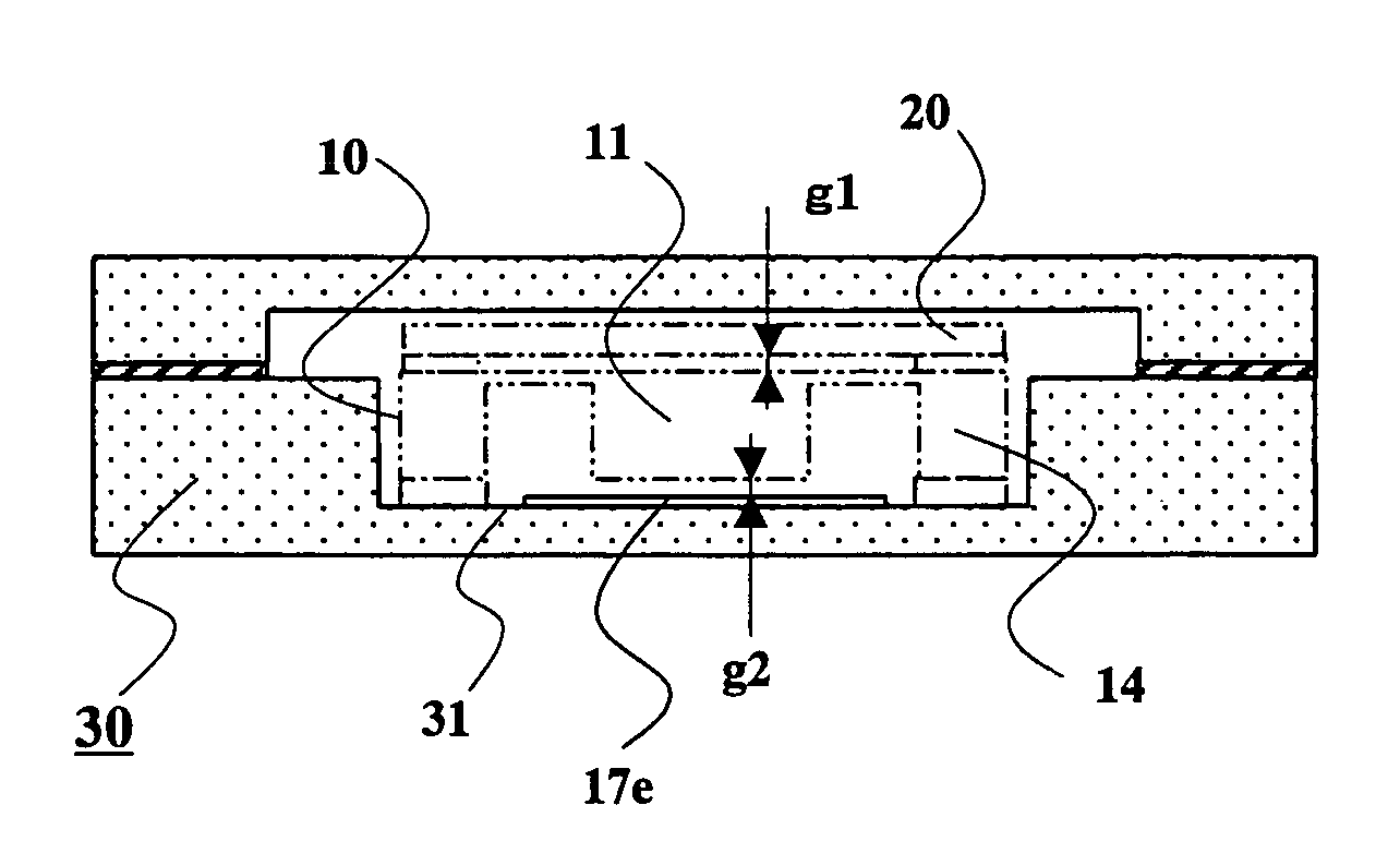
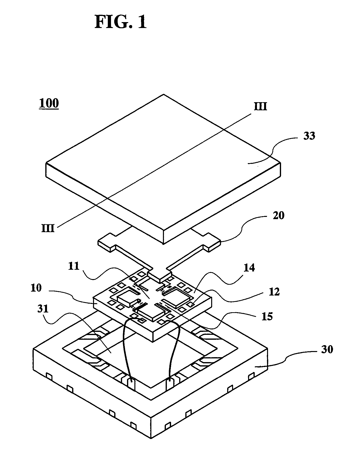
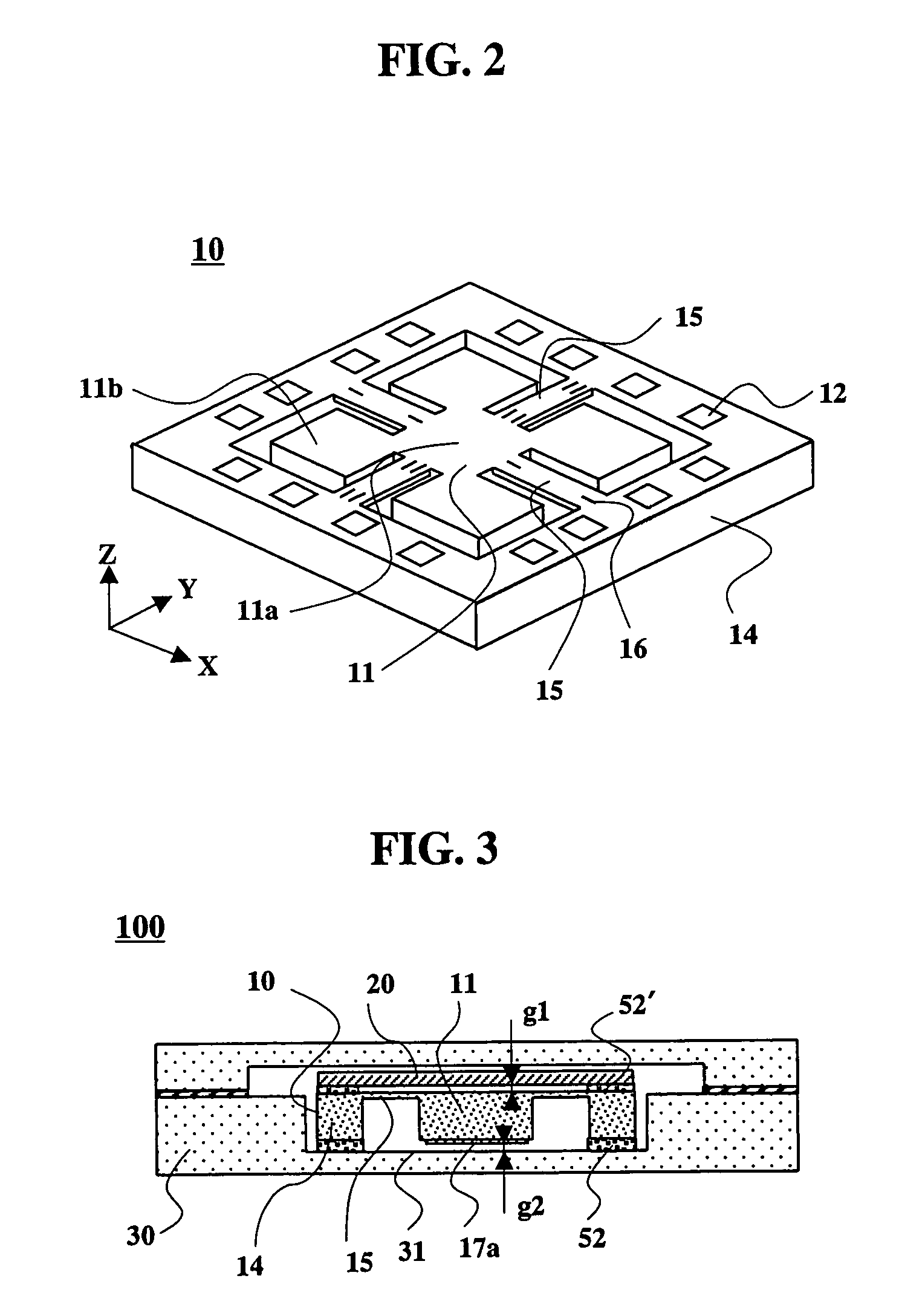
[0042]An embodiment of an acceleration sensor of the present invention will be explained, referring to FIGS. 1 to 4. FIG. 1 shows an exploded perspective view of the acceleration sensor of the present invention, FIG. 2 shows a perspective view showing an acceleration sensor element used in the acceleration sensor of the present invention, and FIG. 3 shows a sectional view taken along the line III-III in FIG. 1. FIG. 4 is a perspective view of the acceleration sensor element shown in FIG. 2, observed from the bottom. In the acceleration sensor 100 of the present invention, a regulation plate 20 made of a soda lime glass of 0.3 mm thick is bonded onto a top surface of the acceleration sensor element 10 by using adhesive 52′ mixed with hard plastic balls (10 μm in diameter), and the acceleration sensor element 10 is inserted into and bonded to a protection case 30 made of ceramic, such as aluminum oxide. As shown in FIG. 4, on a bottom surface of a weight 11 of the acceleration sensor ...

example 2

[0053]The results of the study about relationship of materials and thickness of impact buffer materials with chipping occurrence ratios of their weights are shown in FIG. 5. Acceleration sensors used here had the same structure as that in EXAMPLE 1. Edges of the impact buffer materials 17a were 0.5 μm offset from edges of the bottom surfaces of the weight 11. The impact buffer materials were formed by sputtering, changing material to aluminum, copper, gold, aluminum oxide and silicon nitride and thickness of them from 0.5 μm to 2.5 μm with an interval of 0.5 μm. 2500 to 2800 acceleration sensors having each combination of material and thickness of the impact buffer material were manufactured and tested in the same way as the impact tests explained in EXAMPLE 1, and the chipping occurrence ratios of them were investigated. The 0 μm thickness in the impact buffer materials corresponds to a conventional acceleration sensor. A number of samples were tested because chipping occurrence ra...

example 3

[0057]An acceleration sensor element 10 according to another embodiment of the present invention, shown in a bottom perspective view of FIG. 6, has an impact buffer material 17b made of an aluminum metal layer of 1.3 μm in thickness formed on a whole bottom surface of a weight 11. In the acceleration sensor having the impact buffer material formed on the whole weight bottom surface, corners and edges of the weight bottom surface never directly clash with an inner bottom plate of a protection case, even when a distance between the inner bottom plate of the protection case and the weight bottom surface is relatively large.


PUM


Abstract

An acceleration sensor, which has realized such a high impact-resistance that a weight bottom surface of an acceleration sensor element does not directly collide with an inner bottom plate of a protection case made of ceramic, glass or silicon to avoid edges and corners of the weight bottom surface of the acceleration sensor element chipping, even when an excessive acceleration or impact is applied to the acceleration sensor. The acceleration sensor comprises the acceleration sensor element having in a center a weight that works as a pendulum when acceleration is applied, and the protection case housing the acceleration sensor element. The inner bottom plate of the protection case works as a regulation plate to prevent the weight from excessively swing downwards. An impact buffer material of a metal layer or a resin layer is provided on the weight bottom surface or the inner bottom plate of the protection case.

Description

BACKGROUND OF THE INVENTION[0001]1. Field of the Invention[0002]The present invention relates to an acceleration sensor for detecting acceleration, which is used for toys, automobiles, aircrafts, portable terminals and the like, and particularly to an acceleration sensor superior in impact-resistance.[0003]2. Description of the Related Art[0004]Acceleration sensor elements for use in the acceleration sensor, utilizing a change in physical quantity such as a piezo resistance effect and a change in electrostatic capacity, have been developed and commercialized. These acceleration sensor elements can be widely used in various fields, but recently, such small-sized acceleration sensors as can detect acceleration in multi-axial directions at one time with high sensitivity are demanded.[0005]Since silicon single crystal is an ideal elastic body due to the extreme paucity of lattice defect and since a semiconductor process technology can be applied without large modification, much attentio...

Claims


Application Information

Patent Timeline
Patent Type & Authority Patents(United States)
IPC IPC(8): G01P3/00
CPCG01P1/023G01P15/18G01P15/123G01P2015/0842
Inventor HATANO, HIROYUKITAKADA, YOSHIAKISAITOH, MASAKATSU
Owner HITACHI METALS LTD
Why Eureka
Try Eureka