
Method and conveyorized system for electrolytically processing work pieces

a conveyorized system and work piece technology, applied in the direction of electrolysis components, conductive pattern reinforcement, printed circuit manufacturing, etc., can solve the problems of high cost involved in using such shields, high cost, and inability to protect the trailing edge of printed circuit boards extending transverse to the direction of transpor

Active Publication Date: 2009-07-21
ATOTECH DEUT GMBH
View PDF26 Cites 85 Cited by
  • Summary
  • Abstract
  • Description
  • Claims
  • Application Information

AI Technical Summary

Benefits of technology

[0014]It is therefore the object of the present invention to provide a method and a conveyorized system by means of which the drawbacks described may be avoided.
[0015]It is more specifically an object of the invention to permit electrolytic processing of a succession of work pieces, more specifically of electrical printed circuit boards and other electrical circuit carriers in conveyorized systems, that are spaced any distance apart in their successive order without the described edge effect occurring and without burns being generated during the electrolytic metal-plating process.
[0016]It is moreover a further object of the present invention to make possible that these problems do not occur even if dummies and screening shields are not used, above all while the work pieces are entering and exiting the system and during a change of product, when the electroplating command data, for the current density in particular, are being changed during processing.
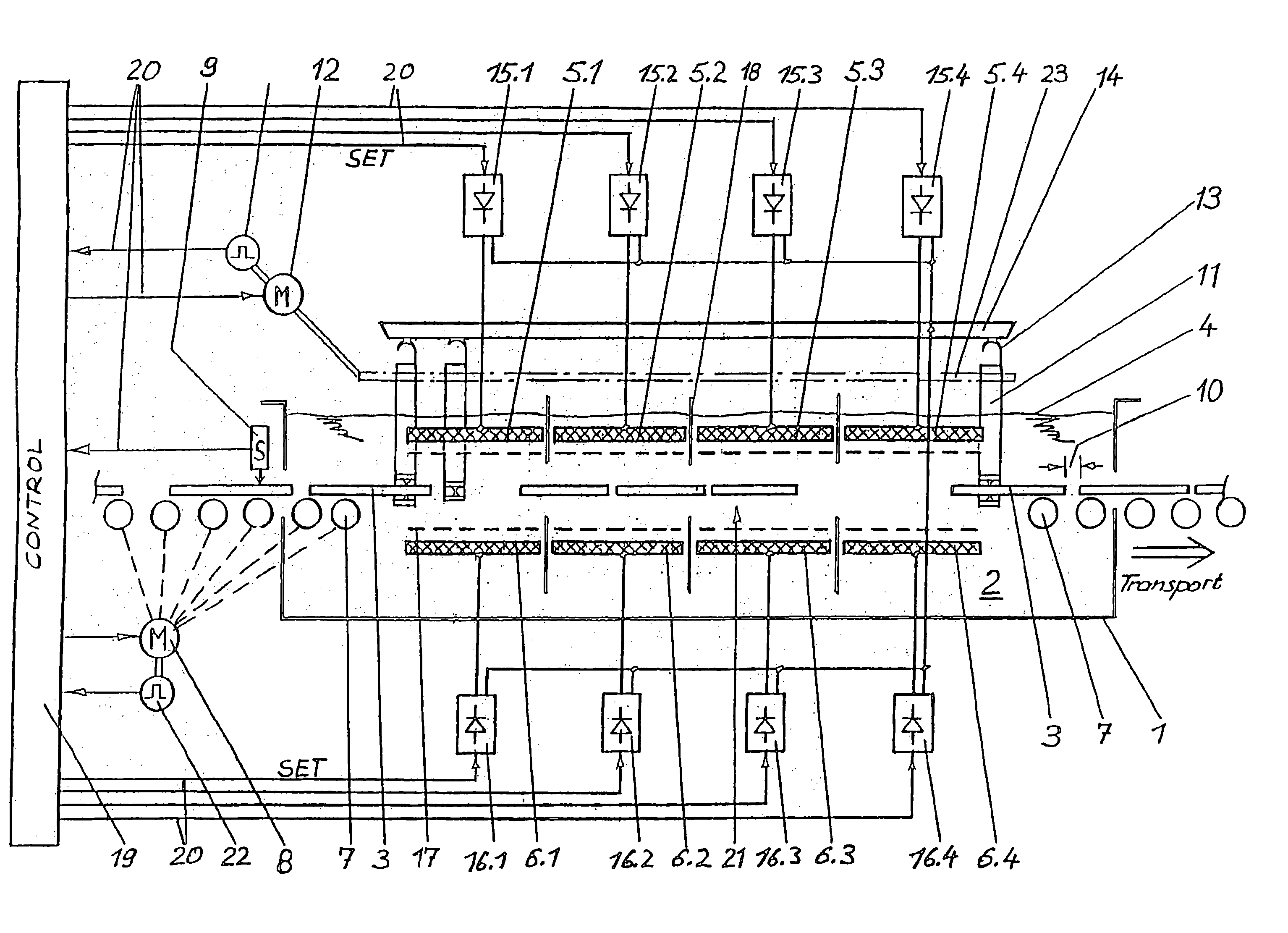
[0032]As contrasted to the method described in DE 39 39 681 C1, the current of the various counter electrodes is not completely turned off when being conducted past the gaps between the work pieces and turned on again once it past them. Here, the current of every single counter electrode is individually controlled and set, the electrolytically to be processed surface area of the work pieces moved past the respective one of the counter electrodes at that moment being taken into consideration for the control thereof. As a result thereof, the current is accurately adjusted according to need as the work pieces are moved past so that the disadvantageous edge-effect on the borders of the work pieces extending transverse to the direction of transport is avoided. Accordingly, it is no longer necessary to use dummies when work pieces are entering or exiting the plant or in gaps between the work pieces for example, when e.g., work pieces are to be processed one after the other under various production conditions. Accordingly, gaps of any size may be provided between work pieces conducted one behind the other through the system without any edge effect even with no dummies placed in these gaps. The currents are computed in the control system from I=J·A (I: current, J: current density, A: area).
[0041]The distance at which the work pieces are conducted past the counter electrodes is preferably selected in function of the electric current density at the work pieces. If for example a high electric current density is set, the distance to be adjusted is to be smaller than when the current density chosen is smaller. By adjusting a relatively small distance between the plane of transportation in which the work pieces are conveyed and the counter electrodes, the edge-effect is reduced since the distance relative to spacings between electrically conductive surface areas on the work pieces is reduced. Since the edge-effect is more specifically experienced at high current density, it is more specifically necessary to reduce the spacings under these conditions.
[0042]As the distance between the counter electrodes and the plane of transportation in which the work pieces are conveyed is relatively small and is to be adjustable to an extremely low value, it is advantageous to provide an electrical insulation permeable to electric field lines between the plane of transportation and the counter electrodes in order to prevent a short between the counter electrodes and the work pieces.

Problems solved by technology

To prevent too high a current density at the edges of the work pieces (edge-effect: increased electric field line density at the edges of the printed circuit boards) it has become known to use technically very complicated, adjustable, electrically isolating shields.
The cost involved in using such shields is high, though.
Another disadvantage of these shields is that, although these shields permit to achieve uniform coating thickness distribution even in the lateral border regions of the electrical printed circuit boards during electrolytic metal-plating, the leading and trailing edges of the printed circuit boards extending transverse to the direction of transport cannot be protected by shields since they are conducted through the plant in a continuous manner, being electrolytically processed thereby.
This leads to coating thickness distribution flaws on the surface thereof which cannot be avoided using the slidable shields described in WO 98 49 375 A2 either.
They are occasioned by a current density which is too high for the electrolyte used.
There, they are co-deposited, which results in a disadvantageous surface roughness.
Although this roughness may be reduced using complicated electrolyte filters, it cannot be avoided altogether.
To fill the plant with dummies is very uneconomical especially when the product to be processed is often changed not the least reason being that a sufficient number of dummies must be available at the plant.
As a result thereof, the dummies are electrolytically processed in excess to the disadvantage of the production boards.
Mostly, the dummies are only scrapped when they risk to damage the plant because they have become too heavy as a result of the great coating thickness or too sharp-edged due to metal nodules for example.
For the reasons mentioned, it is uneconomical and, as a result thereof undesirable, for the operator of a conveyorized system to have to work with dummies in order to avoid the disadvantageous edge-effect.
Today's requirements to higher current densities (12 A / dm2 for example) and narrower, non-usable border areas add to the problem arising from the edge-effect.
Moreover, when the anodes are turned off in this way, the current of the turned off anodes is deviated to the turned on anodes so that metal-plating is carried out at an accordingly undesired higher current density.
However, this technique cannot prevent the at least two printed circuit boards located in front of and behind a gap in the printed circuit board column from being scrap.
As the printed circuit boards are becoming increasingly expensive as a result of the fine line printed circuit technique and the SBU-technique (sequential build up), this scrap is not tolerated either.
If insoluble anodes are used in a chemically etching electrolyte, more specifically when the electrolyte contains compounds of a redox couple, e.g., Fe2+ / Fe3+ compounds, there is a risk that regions of the SBU boards located far from the contacts are etched, that is to say completely destroyed.
That these expensive SBU boards have to be scrapped is not accepted either.

Method used


Image

  • Method and conveyorized system for electrolytically processing work pieces
  • Method and conveyorized system for electrolytically processing work pieces
  • Method and conveyorized system for electrolytically processing work pieces

Examples


Embodiment Construction

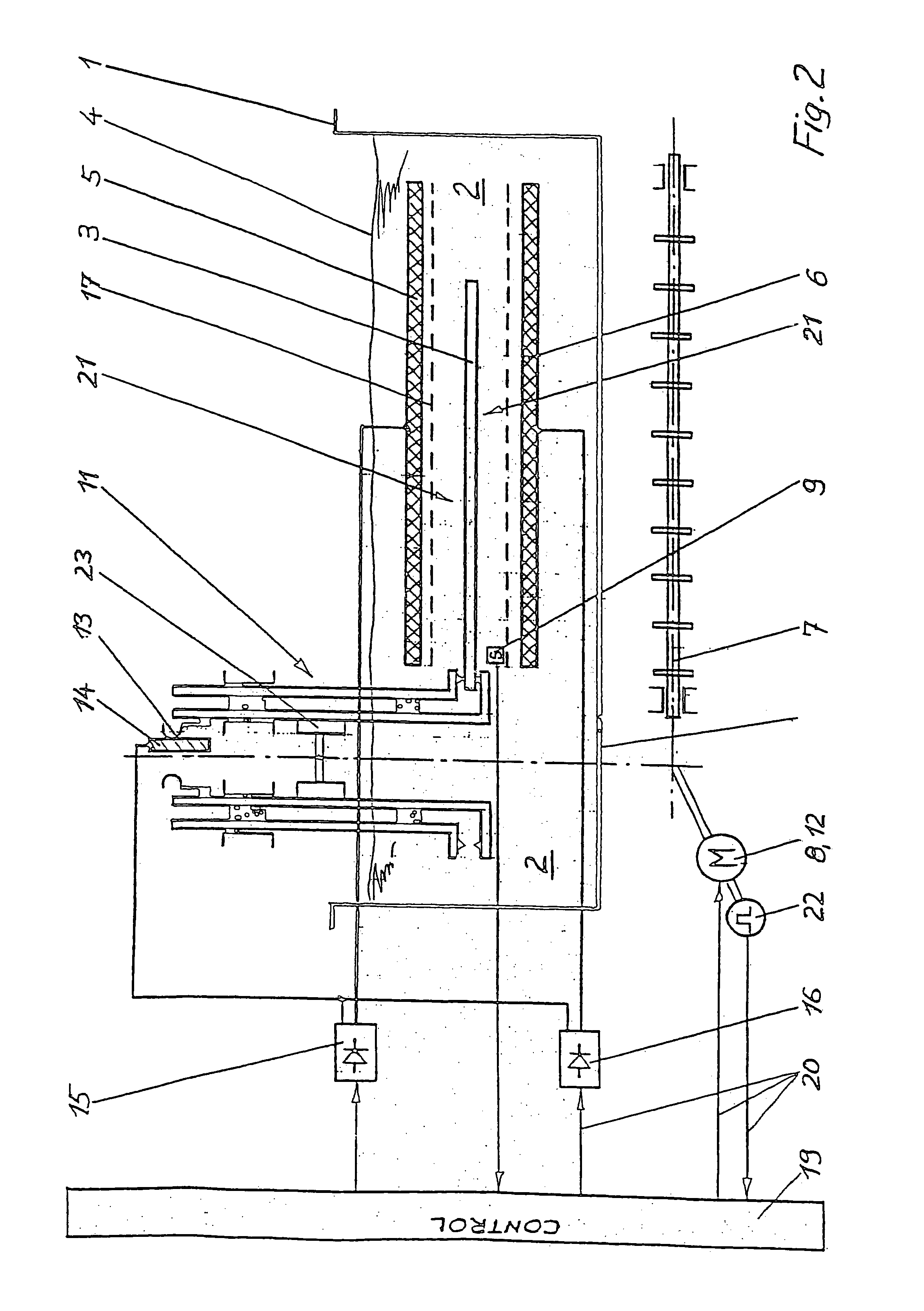
[0053]The conveyorized system in FIG. 1 is provided with a plating tank 1. Said plating tank 1 is filled with an electrolyte 2. The electrolyte 2 is circulated by means of pumps (not shown) and is delivered to the board-shaped work 3. Such conveyorized systems are preferably used in the printed circuit board technique. In the following examples, the work pieces 3 are printed circuit boards or printed circuit films. However, the invention is not limited to the printed circuit board technique.

[0054]The level 4 of the electrolyte 2 extends beyond the upper anodes 5.x (5.1, 5.2, 5.3, 5.4) that are intended to be used for electrolytically processing the upper side of the printed circuit boards 3. The lower anodes 6.x (6.1, 6.2, 6.3, 6.4) serve to concurrently electrolytically process the underside of the printed circuit boards 3. The upper and lower anodes 5.x, 6.x may be soluble or insoluble anodes. The printed circuit boards 3 are introduced into the plating tank 1 through a slot-shape...


PUM

PropertyMeasurementUnit
Lengthaaaaaaaaaa
Timeaaaaaaaaaa
Distanceaaaaaaaaaa

Abstract

In order to avoid an edge-effect (increased electrical field line density at the edges of electrolytically to be processed work pieces) during the electrolytic processing of work pieces 3.x in a conveyorized system, the electric currents originating from various counter electrodes 5.x in the plant are set to values in function of the electrolytically to be processed surface areas of the work pieces 3.x as far as they are located directly opposite the respective ones of the various counter electrodes 5.x. Moreover, the distance between the work pieces 3.x and the counter electrodes 5.x is chosen to be 50 mm maximum. Means 19 for individually controlling and adjusting every single current supply unit 15.x of the counter electrodes 5.x are provided for this purpose. Said means 19 are configured in such a manner that the respective electric currents originating from the various counter electrodes 5.x are settable to values in function of the electrolytically to be processed surface areas of the work pieces 3.x, as far as they are located directly opposite the respective various counter electrodes 5.x.

Description

BACKGROUND OF THE INVENTION[0001]The invention relates to a method and to a conveyorized system for electrolytically processing work pieces, more specifically to a method and to a conveyorized system for processing electrical printed circuit boards and other electrical circuit carriers.[0002]Conveyorized systems as they are utilized in the printed circuit board technique for example substantially comprise a plating tank which is filled with an electrolyte and in which anodes and cathodes are arranged. A transport device conveys the work pieces to be processed through the plant, the work pieces being held in a vertical or horizontal orientation in the case of board-shaped work pieces. The transport device may be a device using transport rolls or transport clamps. For electrolytic etching, the work pieces are anodically and the counter electrodes cathodically polarized. For electrolytic metal-plating, the work pieces are cathodically polarized; the counter electrodes are the anodes. E...

Claims


Application Information

Patent Timeline
IPC IPC(8): C25D21/12B23H7/26C25D17/00C25D17/28H05K3/24
CPCC25D17/28C25D21/12H05K3/241
Inventor HUBEL, EGON
Owner ATOTECH DEUT GMBH
Learn More